1942 - 1947 CHEVROLET SHOP MANUAL
Section 6 - Engine
|
|
|||
|
6-30 |
|||
|
|
|||
 |
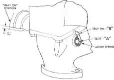
available for service under part No.
6C2799.
To install
this spring, rotate the valve weight toward engine to the "Heat Off" position,
then insert the
anti-rattle spring in slot "A," Fig. 66.
In some
cases it may be necessary to adjust this spring when installing. Hold the weight on
the manifold heat valve shaft
3/16" above the "Heat On" position and bend the spring until it
just touches the stop pin "B," Fig. 66. |
||
|
ENGINE MOUNTINGS
Cushion balanced engine mountings
are used to prevent even the smallest amount of engine vibration being transmitted to the passengers in
the car or
truck.
To adjust the engine mountings,
proceed as follows:
1. Tighten the front engine mounting bolts.
Should the mounting or
mountings be oil soaked
replacement should be made.
2. Tighten the rear engine mounting bolts at
the rear of the transmission
(passenger models only). Make
sure the mounting studs are tight in the transmission
case.
3. Check the clearance between the transmission
cross member and the "U"
section plate (passenger
models only). This clearance should he from .005" to .015", equally spaced fore and
aft. If the clearance exceeds these limits, remove the mounting and bend the "U" section plate
until the clearance is within
the above limits.
NOTE—This clearance is very
important, because it limits the fore and aft movement of the
engine.
4. (On trucks) Tighten the side engine mounting
bracket
bolts.
5. (On passenger models) Remove the bolts from
the engine side mountings and check the clearance between the mounting and its bracket
on each side, if the clearance
is more than 1/16", shim with
3/8" plain flat washer. If the clearance is less than 1/16", loosen the bracket
bolts and push the mounting
upward. (There may be sufficient clearance in the bracket bolt
holes to give the necessary
1/16" clearance). If unable to get the proper clearance in the manner
mentioned above, remove
the brackets and elongate the
holes with a round file until the 1/16" clearance between the mounting and the bracket
is obtained.
NOTE—It is important that
these mountings be set up with an equal amount of tension on each
side. |
|||
|
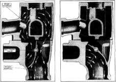
Fig. 65-Manifold Heat Riser and Heat Control
Valve
with the
result that the incoming gases will be expanded several times greater than normal
and it will be impossible to get a normal full charge into the cylinders. This, of course, reduces
power and maximum speed, makes the car lazy on acceleration, etc. Such overheating may also cause
detonation as well as
sticking valves. Therefore, it is most important that the thermostatic spring
be wound up just enough to slip
the end over the anchor pin in
the manifold and no more. This is approximately 1/2 turn of the spring
from its position when unhooked.
Whenever
the manifolds are removed from an engine, the gaskets should be examined to be
sure they are in good
condition, as leaky gaskets will cause the engine to miss. Worn gaskets
should be replaced with new.
In
assembling the manifolds to the cylinder head, the bolts should be drawn up evenly
until they are all tight. A
special wrench is necessary to properly tighten these
bolts.
Exhaust Manifold Valve Anti-Rattle Spring
An
anti-rattle spring for use on the exhaust manifold valve shaft in case a rattle
develops is |
|||
 |
|||
|
Fig. 66-Manifold Heat Valve Anti-Rattle
Spring |
|||
|
|
|||