1942 - 1947 CHEVROLET SHOP MANUAL
Section 6 - Engine
|
|
|||
|
6-35 |
|||
|
|
|||
|
the
surrounding blanket of air passing into the second venturi and this process is repeated
by the air in the main
venturi. By this means the fuel mixture is carried to the cylinders in a
more perfectly atomized
condition. This insulated atomi-zation results in increased smoothness of
operation at both low and high speeds.
The fuel
mixture quality is controlled by a metering rod operating in the metering rod
jet, and operated by the
throttle lever. There are two steps of different diameters on this
metering rod. The larger
diameter, or economy step, is tapered and controls the gasoline flow to about
seven-eighths throttle, at
which time the smaller diameter, or power step, becomes effective,
giving full power for either
high speed or hard low speed pulling. By this simple means both maximum
power and greater economy are
available without changing the
carburetor adjustment. Fig. 71 is a cross-section view of the carburetor
showing the various passages,
jets. etc.
The
carburetor used on all passenger cars and trucks (except cab-over-enginc models) is
identical and is known as the
downdraft "balanced" type. The
air pressure in the carburetor float chamber is balanced with the pressure on the inside
of the air horn by a system of
passages in the carburetor. The
air intake for the balance passage consists of a brass tube pressed into the wall of the
air horn and extending to the center of the air horn. This tube connects with a passage in the side of
the air horn as shown in Fig.
72. With this balanced pressure, the proportions of air and gasoline
in the mixture delivered to the
engine remain substantially the same at all times, even
when the air cleaner is
restricted by dirt.
The choke consists of a one-piece
choke valve, fastened by the means of
two screws to the choke shaft
which is offset to one side of the carburetor air horn. The valve is machined with an
angle on |
each end to permit solid
seating against the wall
of the air horn.
Due to the
choke valve seating against the walls of the air horn, it cannot be
damaged by backfire. The choke lever
is mounted on a boss on the air horn and is retained by a snap ring fitted
into a groove in the
boss.
The choke
lever floats on the shaft and is connected to it through a light coil spring.
This spring hooks to the choke
lever and to the choke shaft. In this way the choke valve is operated by
the choke lever through the spring.
As the
choke button on the instrument panel is pulled out, the light valve spring causes
the valve to follow the movement of the lever, closing the choke valve. As the engine starts, the rush
of incoming air through
the air horn of the carburetor overcomes the tension of this spring and
the valve automatically assumes
the correct position to provide the proper amount of air for the
mixture to enter and prevent
over-choking.
The
accelerating pump consists of a cylinder with a plunger containing an air bell and
two check valves, one on the
inlet and one on the outlet side. The accelerating pump plunger
including the shaft, guide and
leather is made as an assembly. The shaft is rectangular and bears in the
bowl cover. The inlet check valve has a bakelite disc while the outlet check valve has a brass
disc. The brass disc aids fuel economy since its weight tends to keep it on its scat and prevent lifting
from the seat due to the air
velocity in the carburetor.
The upward
movement of the pump plunger, when the
throttle is closed, draws a small metered quantity of gasoline into the bottom of the
cylinder. The slightest opening of the throttle
(downward movement of the
plunger) causes an immediate discharge through the pump jet
pointing downward into the main
venturi. This action is illustrated in Fig. 73.
Gasoline
enters the low speed jet through a 3/64" hole drilled through the jet at the recess
between the threaded
section and the base of the jet. which coincides with the low speed well in
the carburetor body, Fig. 71.
The metering hole is drilled
vertically and is .035" in diameter. This design prevents the possibility of the
engine stalling due to
gasoline surging away from this jet when the brakes are applied
suddenly.
The main
nozzle is of two-piece construction with the inner nozzle pressed into the outer
nozzle, thereby maintaining
the proper relationship between the openings in the walls of the two
nozzles. The nozzle assembly is held in place by a brass plug
having a 1/8" hole drilled through its
center. |
||
 |
|||
|
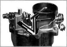
Fig. 72—Carburetor Balance
Passages |
|||
|
|
|||