1942 - 1947 CHEVROLET SHOP MANUAL
Section 6 - Engine
|
|
|||
|
6-43 |
|||
|
|
|||
|
Inspection
After completing the disassembly
operations, thoroughly wash all parts
in clean gasoline or cleaning
solvent. Blow out all drilled passages in the carburetor body with compressed air in
the opposite direction to normal How of air or gasoline. Inspect and make sure the idling ports,
idle air bleed passage, and the
vacuum spark advance port are
free from carbon deposits or dirt. Check the vacuum power jet piston in its cylinder to
make sure it is free.
NOTE—Should the piston stick in
the cylinder the vacuum power jet may be in operation at all speeds. This,
of course, would result in poor gasoline economy.
Disassemble the power
jet and clean it thoroughly. Any
dirt in this jet may either stop the |
flow of gasoline at high speeds,
and result in poor performance, or the
dirt might hold the valve off its seat, and cause the power jet to be in
operation at all speeds. This, of course, would result in poor
economy.
Inspect the
accelerating pump intake and discharge check valves to make sure the ball
checks are free and seating properly. Inspect the needle valve and scat, low speed jet, main nozzle
air bleed, and main metering jet to make sure they are thoroughly
clean.
Reassembly
1. Install the main metering jet in the
carburetor body.
NOTE—There are four (4) jets
released for service for making adjustments—Part No. 603947. one-step
lean; Part No. 603948, second-step lean; Part No. 603949, third-step lean;
Part No. 603950, one-step rich.
2. Install the main nozzle idle jet and main
nozzle air bleed in the carburetor body.
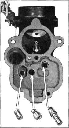
3. Install the accelerating pump intake and
discharge check valves,
vacuum power jet and tighten
them securely. Fig. 90.
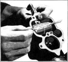
4. Install needle valve and float, assemble
float lever pin and plug
assembly. To check the float level measure from the machined surface of
the float chamber, with the gaskets removed, to the top of the float while holding the lip of
the float lever firmly against
end of the seated needle valve.
Proper float level is from 1/32 of an inch to 1/16 of an inch below top
of float chamber. Fig. 91. |
||
 |
|||
 |
|||
|
|
|||
|
Fig. 90—Carburetor Jet Installation |
Fig. 91-Checking Float Level |
||
|
|
|||