1942 - 1947 CHEVROLET SHOP MANUAL
Section 7 - Transmission
|
|
|||
|
7-20 |
|||
|
|
|||
|
top holes
support the transmission during this operation and prevent damage to the clutch
disc.
6. Remove the transmission and
place it in the
transmission bench
stand.
DISASSEMBLY OF THE
TRANSMISSION (1/2, 3/4 and 3/4-Ton Special Trucks)
1. Mount transmission in holding
fixture.
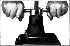
2. To remove the gearshift lever, slide the
open side of the K-353 gearshift lever remover and replacer over the
lever, engage the lugs of the tool in the open slot of the retainer, Fig.
34. Then press down on the tool and turn it to the left to disengage the
lugs on the retainer. Lift the
lever out of the cover. |
9. The
bearings can be removed from the main shaft and from the clutch gear by
supporting the inner race of each
bearing on an arbor press and
pressing on the end of the shaft until it is free of the
bearing.
Fig. 35 is a layout of the
four-speed transmission parts. This figure shows the back end construction
for Hotchkiss drive (items 31, 32 and
33) as used on the 3/4-ton long Wheelbase panel and all
1-1/2-ton trucks including
Cab-Over-Engine models.
INSPECTION
After the transmission has been
completely disassembled all
parts should be thoroughly washed in clean gasoline or cleaning
solvent and inspected for wear or damage.
All bearings should be thoroughly
cleaned, oiled with light engine oil,
and checked for scored races or worn balls or rollers. To check the
bearings for excessive looseness or for roughness, hold the inner race in one hand and turn the outer race
slowly in the other hand. DO
NOT spin bearing with compressed air.
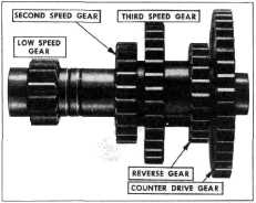
COUNTERSHAFT AND IDLER GEARS
Should it
be necessary to replace the gears on the countershaft, the old gears should be
pressed off on an arbor press
and the new gears pressed on the shaft. When reassembling the gears to the
countershaft, care must be used
to place the gears in correct position on the shaft and also to install
the three spacers in their
proper place between the gears.
The chamfered side of the second-speed gear faces the low-speed gear. The chamfered
side of the third-speed gear faces the chamfered side of the reverse gear. The illustration, Fig.
36. shows the order in which the gears are pressed on the shaft. |
||
 |
|||
|
Fig. 34—Removing Gearshift Lever
3. Remove the transmission cover assembly and
place the transmission in two gears at once to lock the shafts.
4. Remove the speedometer driven gear and shaft
and with a long shank wrench remove the capscrew holding the universal joint to the
rear end of the transmission
main shaft. Remove the
universal joint; then remove the capscrews holding the rear bearing retainer and
remove the retainer from the
transmission case.
5. Remove the clutch gear bearing retainer and
drive out the clutch gear and
bearing, using a soft steel
drift to avoid damaging the teeth of the gear.
6. Remove the main shaft pilot bearing and
drive out the main shaft and
bearing through the rear end of
the case. Remove the sliding gears.
7. Drive out the reverse gear idler shaft from
the front to the rear
and remove the reverse idler gear.
8. Drive the countergear to the rear to remove
the rear bearing and its
retainer. Remove the countergear and drive out the countershaft
front bearing and retainer by
tapping lightly around the
outer race of the bearing. |
|||
 |
|||
|
36.—Countershaft and Gears |
|||
|
|
|||