1942 - 1947 CHEVROLET SHOP MANUAL
Section 12 - Electrical System
|
|
|||
|
12-28
|
|||
|
|
|||
 |
 |
||
|
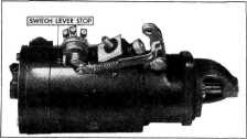
Fig. 58-Polarity Reversing Switch an Starting
Motor
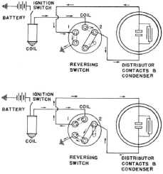
The diagrams. Fig. 59,
show the connections and operation
of the switch. These two diagrams show the two directions of
current flow through the primary
circuit, one or the other is always in operation.
The purpose of this arrangement is to produce
uniform wear on both distributor contact
points, thereby increasing point
life.
|
|||
|
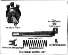
Fig. 60-Reversing Switch Parts
All parts of the reversing switch are serviced.
Figure 60 is a layout of all
parts comprising the complete switch unit.
Always be sure the battery positive cable is
attached to the starter switch so
that the cable leads
straight up from the rear of the terminal (in
such a manner that it will not
obstruct the starter shift
lever when starting the engine), to prevent
any possibility of the cable
interfering with the
reversing switch operating linkage.
Checking Switch Operation
Proper operation of
the reversing switch is essential
to the flow of primary current through the
ignition system. If for any reason
current fails to flow through the switch, the ignition system will
fail to function. Should there be any question about the proper
functioning of the switch, it should be checked as follows:
1. With
the breaker points closed, turn on ignition
switch. If primary circuit is closed, the instrument
panel ammeter will indicate the ignition
load.
2. Slowly
push down on the starter pedal while
watching the ammeter. As the
pedal is partially
depressed and the reversing switch begins to
operate, the ammeter hand will
return to zero.
3.
Continuing to depress the starter
pedal should again complete
the primary circuit through the
reversing switch and cause the
ammeter to register as in
paragraph 1 above.
4. Additional
movement downward on the starter
pedal will cause the reversing
switch to "click," the
ratchet locking into the closed circuit position.
Further movement of the pedal beyond
this point will be absorbed by
the over-travel spring and
should have no effect on the reversing
switch.
|
|||
 |
|||
|
Fig. 59-Reversing Switch Circuits
|
|||
|
The switch has a positive stop for the forward movement or travel of
the switch lever, insuring proper
travel of the lever when the starter lever is
depressed to start the engine. The
operating linkage consists of a connector lever, from the
starter shift lever to the switch
lever, made of a flat stamping with a spring loaded sliding
section to prevent any possibility
of bending when the switch lever
contacts the stop. The reversing
switch must always be
assembled to the starting motor with
the switch lever down as shown in
Fig. 58.
|
|||
|
|
|||