1942 - 1947 CHEVROLET SHOP MANUAL
Section 4 - Rear Axle, Universal Joints & Springs
|
|
|||
|
4-11 |
|||
|
|
|||
|
bolts. This permits ring gear
replacement without changing the differential case. The differential
bearings are of barrel roller type.
The front pinion bearing is a
large double row ball bearing, and the rear pinion bearing is a large
roller bearing. A spring-loaded rawhide oil seal is used at the rear of
the universal joint yoke.
The axle shaft to wheel hub gasket
is made of soft sheet aluminum to reduce friction and load on the bolts. A
lock plate is used to lock these bolts.
Identification of Rear Axles
The regular production 6.17 to 1
rear axle ratio may be identified by the serial number stamped on the top
right-hand side of the differential carrier and prefixed by the letters
"2AR," "2AS," "BR" or "BS."
The optional ratio 5.43 to 1 may
be identified by the letters "2AT," "2AW" or "BT" prefixed to the serial
number.
MINOR SERVICE OPERATIONS
Axle Shaft Removal
1. With a cold chisel and hammer bend the lugs
of the lock plate away from the
bolt heads.
2. Remove the eight 1/2" capscrews and
lock plate.
3. Install two 7/16"Ś14 capscrews in the
threaded holes provided in the
axle shaft flange. By turning these capscrews alternately the axle
shaft may easily be removed.
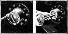
Remove the axle shaft and
aluminum gasket, Fig. 16. |
NOTEŚRemoval of the wheel is
important; it prevents damage to the oil seal and permits more accurate
adjustment of the bearings.
2. Raise the lip of the special
lock from the notch in the lock nut.
Remove lock nut with special wrench J-870, and remove the lock,
inner adjusting nut, and thrust washer. |
||
 |
|||
|
Fig. 17ŚRemoving Inner Bearing and Oil
Seal
3. Remove the hub and
drum assembly.
4. Install brake wheel cylinder clamp to
prevent the brake fluid from leaking should the brake pedal be accidentally
depressed.
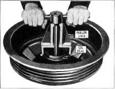
5. To remove the inner bearing and oil seal,
use puller
J-918. |
|||
 |
|||
 |
|||
|
Fig. 18ŚRemoving Outer Bearing Snap Ring
The puller is installed by tilting
the plate with the chain attached, so that it may be slipped through the
bearing and engage the outer race of the bearing. The plate is then held
in this position by the chain while threading the puller shaft into the
tapped hole. The puller body is then located against the housing and the
bearing assembly and oil seal are removed by turning the puller
handle, Fig. 17.
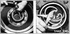
6. To remove the outer bearing,
first tap the outer race to relieve
the tension at the snap ring; then remove the snap ring on the
inside of the hub, Fig. 18. Remove the bearing by
driving |
|||
|
Fig 16ŚLoosening and Removing Axle Shaft
Axle Shaft Replacement
Place a new aluminum axle shaft
flange gasket on the axle shaft and push the shaft into the housing.
Use a new lock plate at the axle shaft capscrews and insert the eight
capscrews in the axle shaft flange, tightening them alternately and make
sure they are pulled up tight. Then bend the tangs of the lock plate
against the heads of the capscrews.
Removal of Rear Wheel Bearings
1. Jack up the rear axle and
remove the wheel and axle shaft. |
|||
|
|
|||