1942 - 1947 CHEVROLET SHOP MANUAL
Section 4 - Rear Axle, Universal Joints & Springs
|
|
|||
|
4-18 |
|||
|
|
|||
|
On the
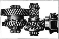
double reduction shaft are the two double reduction pinions, each of which has an
integral spur pinion on its
inner side. Between them are two sets of short splines integral with the
shaft, and a floating shifter
sleeve that is moved by a shifter mechanism to lock one set of splines
on the double reduction shaft
with the spur pinion on one or
the other double reduction pinions.
The control is operated by a lever
in the cab and connected to the
shifter lever on the axle by cable and rod linkage. As the shifter
lever in the cab is moved to the
forward position, the shifter sleeve is moved to the right, locking
the double reduction high-speed
pinion to the double reduction shaft, at the same time disengaging the double
reduction low-speed pinion, permitting it to turn freely on the
shaft. The power from the engine is
then transmitted through
the propeller shaft, pinion and ring gear, then to the double reduction
shaft and high-speed pinion.
Thence to the high-speed double reduction gear through the
differential to the rear axle
and wheels, Fig. 33. |
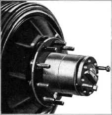
screws
alternately, the axle shafts and aluminum gaskets can be removed from the wheel hub,
Fig. 34.
Remove the
capscrews which fasten the differential carrier to the axle housing
and place a jack under the carrier.
The assembly can now be removed from under the
truck. |
||
 |
|||
 |
|||
|
Fig. 34—Axle Shaft Removal
Differential and Carrier Disassembly
Place the
assembly in a bench vise by clamping on the lower rib of the carrier. Remove the
cotter pin, nut and washer
from the end of the pinion shaft. The universal joint yoke may then be
removed from the shaft.
Before
removing the differential assembly from the carrier, mark the differential bearing
caps and adjusting nuts with a center punch for position identification when reassembling. This is
important because the caps are machined in place.
Remove the tie wire, differential
bearing adjusting nut locks and
the bolts from the bearing caps. Remove the bearing caps and
differential assembly from the
carrier.
To remove
the pinion cage and bearing assembly, remove the nuts which retain the cage
to the carrier.
NOTE—There are two tapped holes
in the flange of the cage for use when removing a tight cage. It Is most
important when removing the pinion cage and the double reduction shaft
bearing caps that that number and thickness of the shims be checked for
reference when reassembling. This will save considerable time when making
adjustments. |
|||
|
Fig. 33—Two-Speed Axle Operation [High Gear)
When the
shifter lever is moved backwards the shifter sleeve is moved to the left,
disengaging the double
reduction high-speed pinion and transferring the power through the low-speed pinion
and low-speed gear to the rear
axle and wheels.
REPAIR OPERATIONS
Wheel hubs,
bearings, oil seals, and axle shafts are serviced in the same manner as on the
conventional 1-1/2-ton truck rear axle.
Removal of the Differential and Carrier
Remove the
two trunnion bearing "U" bolts from
the rear yoke. Split the universal joint, shift the propeller shaft forward and allow the
rear axle propeller shaft to drop down.
Remove the
capscrews and locks which retain the
axle shaft flange to the wheel hub.
Install two 7/16"-14 cap screws in
the holes provided in the shaft
flange and by turning the cap |
|||
|
|
|||