1942 - 1947 CHEVROLET SHOP MANUAL
Section 6 - Engine
|
|
|||
|
6-13 |
|||
|
|
|||
|
shaft by
pressure on any part of the composition.
The thrust
bearing, on the inside of the camshaft gear, when assembled to the camshaft,
determines the amount of
camshaft end play.
If there is an excessive amount of
camshaft end-play, it is necessary to remove the gear and shaft assembly and press the gear farther on the
shaft so that the thrust plate
is tight, yet free to revolve to a maximum of .003" clearance, Fig.
21.
When the
camshaft and gear are assembled to the
engine, it is important that the punch marks on both the camshaft and the crankshaft
gear be lined up, directly
opposite each other.
The
camshaft will then be in its proper position and the valves will open and close in
proper relation to the
movement of the pistons. |
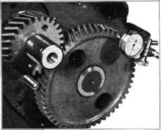
gear for
run-out with a dial indicator. This should not exceed .003". Then check the run-out of
the camshaft gear. This should
not exceed .004". The method of
checking run-out is illustrated in Fig. 22.
If timing
gear run-out is greater than specified above, remove the gear and check for burrs
on the shaft or gear that
might cause the condition. If unable to overcome the trouble in this
manner, replace the gear at fault with a new one.
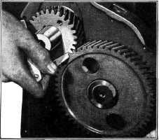
Back-lash
between the timing gear teeth should be checked with a feeler gauge as shown in
Fig. 23. The back-lash should
not be less than .002" nor more
than .005".
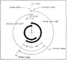
Valve Timing
Fig. 24 is the valve timing
diagram for all 1942 engines. Note
that the intake valve starts to open 3 degrees before upper dead center and
remains open for 218 degrees, closing 35 degrees past lower dead center. |
||
 |
|||
 |
|||
|
Fig. 22-Checking Run-Out of Timing Gears
After the
camshaft and crankshaft gears are in their proper places, check the
crankshaft timing |
|||
 |
|||
|
Fig. 24—Valve Timing Diagram
The exhaust
valve starts to open 46 degrees before lower dead center and remains open for
231 degrees, closing 5 degrees
past upper dead center.
To check
the valve timing, use number 1 cylinder exhaust valve.
1. Tighten the adjusting screw to just remove
all tappet
clearance.
2. Hand crank the engine until the number 1
cylinder exhaust valve
starts to close. Continue cranking the engine until the triangular
mark on the flywheel lines up
with the pointer in the flywheel housing.
3. Mount a dial gauge on the rocker shaft
support with the spindle
of the indicator on top of |
|||
|
Fig. 23—Checklng Timing Gear
Back-Lash |
|||
|
|
|||