1942 - 1947 CHEVROLET SHOP MANUAL
Section 6 - Engine
|
|
|||
|
6-15 |
|||
|
|
|||
|
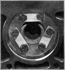
HARMONIC BALANCER
The harmonic balancer consists of
a small flyweight attached to
and driven by the crankshaft through two rubber annular rings mounted
over six studs riveted to the hub.
When the
engine is running, any change in the speed of the crankshaft, which would cause
vibration, will be
resisted by the action of the balancer. This resistance is produced by a floating
action between the rubber annular rings and the six driving
studs. The flyweight moves back and forth on the rubber mounted studs in
the opposite direction to that of the
crankshaft, and thereby dampens out or absorbs crankshaft
vibrations.
Due to the
construction of the balancer the parts are not serviced separately. The
1942 harmonic balancer is
interchangeable with 1941 models but not with previous models, due to a
difference in length.
The
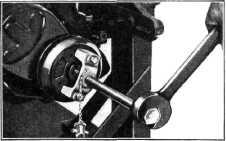
harmonic balancer puller, Fig. 28, is made in three parts, a drop forged puller body, a
puller screw and a driver head. The driver head is made of tool steel with a drill rod pin which is
replaceable. |
FLYWHEEL
Chevrolet flywheels are made from
the very best grade of cast iron, and
have a steel ring gear shrunk on the outer diameter, with which the
starter drive pinion meshes when starting the engine.
The
flywheel is accurately balanced to assure smooth engine operation at all speeds, and
is properly located on the
crankshaft flange by three dowels. Attachment to the crankshaft is by
six special large head cap
screws locked by lock plates.
Fig. 29. |
||
 |
|||
 |
|||
|
Fig. 29-Method of Locking Flywheel Bolts
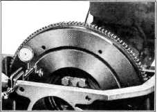
After the flywheel has been
assembled to the crankshaft, it is
necessary that the face and the rim of the flywheel be checked for
run-out. |
|||
|
Fig. 28—Harmonic Balancer Puller and Driver
In
operation the puller body is attached to the balancer by means of the two cap screws in
the puller, which screw into the tapped holes in the balancer. This
insures the puller body being held firmly against the balancer and helps to
hold the balancer together while it is being removed. Next turn the puller screw into the body until
the balancer is removed. This puller provides a steady
pull on the balancer allowing
its removal without damage.
When installing the balancer the
puller body is removed, the driver
placed in the starting crank jaws and the puller body reassembled to the
balancer. Next line up
the key in the crankshaft with the keyway in the balancer and drive the
balancer in position using the
puller screw as a driver. If the puller is assembled in any other
than this way serious damage will be
done to the balancer. |
|||
 |
|||
|
Fig. 30-Checklng Flywheel Run-
Out |
|||
|
|
|||