1942 - 1947 CHEVROLET SHOP MANUAL
Section 6 - Engine
|
|
||||
|
6-39 |
||||
|
|
||||
|
7. Loosen
the three screws attaching the air horn to the carburetor body. Remove the main
nozzle passage plug. Remove the
main nozzle screw plug. Then,
using a screwdriver, reach down through the air horn and press on the
"D" section of the main
nozzle—this will force the main
nozzle out of the "D" section in the primary venturi.
CAUTION—Do not press on the end
of the main nozzle.
Remove the
air horn screws and air horn. S.
Remove the low speed jet. 9. Remove the passage plug and screen for
the
accelerating pump check valves.
Then remove
the inlet and outlet
valves.
10. Remove the passage plug for the
accelerating pump jet, then remove the jet.
11. Remove the idle adjusting screw and the
idle port passage
plug.
In most
cases it will not be necessary to remove the choke valve or throttle valve,
however check the
operation of the choke mechanism. If necessary it may be disassembled
by removing the two screws
attaching the choke valve. The
choke lever and spring may be removed by first removing the snap ring
retaining the lever to the boss on the air horn.
Inspection
1. Wash all parts thoroughly in clean gasoline
or cleaning
solvent.
2. Check the idle ports and first by-pass for
carbon deposits. Then
blow out all drilled passages with compressed air in the opposite
direction to that of
normal flow of air or gasoline.
3. Inspect the main nozzle for burrs on the
venturi end. Blow out the
low speed jet and make sure the
metering hole in the jet is clean.
4. Check the operation of both the inlet and
outlet check valves.
Inspect the accelerating pump jet to make sure it is
clean.
5. Inspect the accelerating pump plunger. If
the leather or its expanding
spring are damaged in any way,
the plunger assembly should be replaced.
6. Inspect the metering rod jet and metering
rod for wear or damage and to
make sure it is the correct metering rod for the
carburetor.
Reassembly
1. If the throttle valve was removed care must
be used to make sure the letter "C" stamped on the valve is toward the idle port when
reassembling, Fig. 80.
2. If the choke valve has been removed, it must
be assembled to the shaft with
the letter "C" stamped on the valve toward top of air
horn. |
 |
|||
|
Fig. 80—Correct Assembly of Throttle Valve
3. Assemble the air horn loosely to the
carburetor body, making
sure the small gasket is in place at the balance
passage. |
||||
|
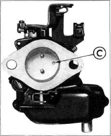
4. Assemble the copper gasket on the main nozzle, (4) Fig. 82, Hold the carburetor with the air horn down, line up the "D" section on the end of the nozzle with the "D" opening in the primary venturi and drop the nozzle (5) into the opening. Install the nozzle screw plug (3) and
|
 |
|||
|
tighten it
securely. |
||||
|
Tighten the
three |
Fig. 81— Checking Seat on Low
Speed Jet |
|||
|
air horn
screws. Install the main nozzle
passage plug (1) using a new copper gasket
(2).
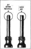
5. Install the low speed jet (13) and gasket
(12), in the carburetor body, tighten in place,
then again remove the jet and
check the bearing on the top
end.
If there
is a complete bearing around the top of the jet indicating a full seat, it may be
reinstalled, Fig. 81. If the
bearing is incomplete a
new jet should be installed. |
||||
|
|
||||