1942 - 1947 CHEVROLET SHOP MANUAL
Section 7 - Transmission
|
|
|||
|
7-7 |
|||
|
|
|||
|
2. Blow out the bearings with compressed
air.
CAUTION—Do not allow the
bearings to spin, but turn them slowly by hand. Spinning bearings
will damage the races and balls.
3. After making sure the hearings arc clean,
lubricate with light
engine oil and check them for wear or roughness. Roughness may be
determined by slowly
turning the outer race by hand
Transmission Case
Wash the
transmission case inside and outside with gasoline or cleaning solvent and
inspect for cracks. Inspect
the front face which fits against clutch housing for burrs and if any are
present, dress them off with a
fine cut mill file.
Gears
1. Inspect all gears and, if necessary, replace
any that are worn or damaged.
2. Check the first and reverse sliding gear to
make sure it slides freely on
the clutch sleeve.
3. Check the clutch sleeve to see that it
slides freely on the
mainshaft.
4. Check the synchronizing cones for wear or
for being loose in the clutch
sleeve. If the cones are damaged in any way, it will be necessary to
replace the clutch sleeve
assembly and both synchronizing rings.
Synchronizer Rings
1. Inspect the synchronizer rings for
smoothness.
2. Place the synchronizer rings in the
synchronizing cones and
check with the thumbs to see that the rings do not rock.
Excessive
rocking indicates a poor fit between the ring and cone, which will not permit
proper synchronizing of the gears during shifting.
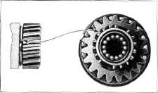
Synchronizer Energizing Springs
1. It will be noticed upon examining these
springs that one of the ends
is slightly offset. Each spring must be assembled in its groove in
the clutch gear and the second
speed gear with the offset or
locking end between the third and fourth teeth of either of the two banks of
teeth on these gears, thus keeping the spring from turning in its groove, Fig. 10. The gap in
the spring must not be in line
with the opening between
either bank of teeth on either gear mentioned.
2. Under normal operation it should never be
necessary to replace the
energizing springs; however, should an energizing spring be removed
for any reason, a new spring
should be installed. |
 |
||
|
Fig. 10—Correct Position of Energizing Spring
The spring
may be removed by slipping a thin blade under the spring and raising it
over the clutch teeth on the gear and
slipping it off over
the
teeth.
CAUTION—In replacing either
energizing spring, be very careful not to distort the spring when
expanding it over the clutch teeth.
Bushings
1. The
bushings used in the countergear and the idler gear are pressed into the gears, then
peened into holes in the bores,
to lock them in place, and are accurately bored with special
diamond boring tools. This
insures the positive alignment of the bushings and their shafts as
well as the proper meshing of the
gears. Because of the high
degree of accuracy to which these parts are machined the bushings are not
serviced separately, but
as a part of the gear assembly. |
|||
 |
|||
|
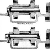
WRONG ANGLE |
|||
|
Fig. 11—Reverse Idler Gear, Shaft and Lock
Pin |
|||
|
|
|||