1942 - 1947 CHEVROLET SHOP MANUAL
Section 7 - Transmission
|
|
|||
|
7-10 |
|||
|
|
|||
|
INSPECTION
1. Wash all parts in clean gasoline or cleaning
solvent.
2. Inspect the shifter forks. Make sure they
slide freely on the guide
bar.
3. Inspect all parts for
wear.
REASSEMBLY
1. Install
the long shifter fork on the guide bar with the fork end toward the nearest guide
bar mounting screw hole, making
sure to line up one shift lock
recess in the fork with the hole drilled through the guide bar. Install one
ball and the spring in the
guide bar hole. Start the other shifter fork on the guide bar and
assemble the other ball on the
spring. Fig. 16. |
With a finger on the end of the
operating shaft, press the shifter yoke lever firmly against the selector bell crank. Then assemble the guide
bar and shifter fork assembly
to the cover with the low and
reverse shifter fork toward the narrow side (bottom) of the cover. At the
same time make sure the
selector bell crank fits into
the slots in the shifter forks and that the slots in the ends of the shifter yoke
lever fit over the pins in the
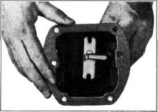
forks. Bolt the guide bar to the cover, Fig. 18. When assembling
the |
||
 |
|||
 |
|||
|
Fig. 18—Assembling Guide Bar and Shifter Forks to
Caver
cover and
shifter fork assembly to the transmission, the low and reverse sliding gear
and the clutch sleeve must be
in the neutral position because the guide bar is piloted in the
transmission case. A new gasket
should be used between the cover and transmission when assembling.
6. Check the operation of the transmission by
shifting all
gears.
7. Install transmission in the
car.
1/2, 3/4 AND 3/4-TON
SPECIAL TRUCKS |
|||
|
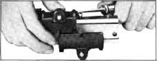
Fig. 16—Installing Shifter Forks on Guide Bar
2. With a flat tool compress the spring until
the ball is in the hole in the
guide bar. Keeping the spring
compressed, slide the fork over the ball and move both forks to their neutral
position.
3. If the operating shaft cork seal and its
retainer are worn or damaged,
they must be replaced.
4. Assemble the operating shaft to the cover,
and then assemble the
anti-rattle spring and shifter yoke lever to the bell crank end of the
operating shaft. Install
selector bell crank and lever.
Move the selector bell crank over the center of the shifter yoke lever, Fig.
17. |
|||
|
Service
operations for the 1/2, 3/4 and 3/4-ton special truck transmissions are the same as
those for the passenger car
transmission except for the reassembly of the roller bearing
countergear, and disassembly and reassembly of the cover and
shifter mechanism. Fig. 19 shows this transmission assembly in cross-section.
Disassembly
of the roller bearing countergear is the same as on the passenger car
transmission. The following
procedure covers countergear installation.
Countergear Reassembly
1. Place
some cup grease in the roller bearing area of each end of the countergear. Install
the 25 rollers in each end.
The grease will hold the rollers in place while placing the gear in
the |
|||
 |
|||
|
Fig. 17-Selector Bell Crank in Center of Shifter
Yoke |
|||
|
|
|||