1942 - 1947 CHEVROLET SHOP MANUAL
Section 7 - Transmission
|
|
|||||
|
7-9 |
|||||
|
|
|||||
|
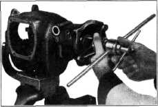
3. |
Turn the yoke of the mainshaft
removing and replacing tool, J-938, down on the threads and screw the tool
shaft into the threaded end of the mainshaft. Bolt the yoke of the tool to
the rear face of the transmission case.
Turn the tool handles
counterclockwise until the mainshaft is seated in the rear bearing, Fig.
13. The proper seating of the shoulder on the |
5. Using a soft steel drift, tap the clutch
gear bearing on the outer race
until the bearing locating ring
seats against the case, being careful to drive the assembly straight to
prevent damage to the mainshaft
pilot and pilot bearing.
CAUTION—During this operation
make sure that the synchronizer ring lugs line up with the slots between
the clutch teeth on the clutch gear.
6. Install the clutch gear bearing retainer,
making sure that the oil slot
in the retainer lines up with
the oil slot in the front face of the transmission case. Do not allow the gasket to
protrude beyond the edge
of the retainer.
7. Install the retainer screws, using the
special shakeproof lockwasher.
Draw the screws up evenly.
8. Check the transmission in all gears to be
sure that there is no
indication of a bind in any position.
Universal Joint
1. Install the spacer and speedometer drive
gear on the mainshaft and
slide the front yoke of the
universal joint on the main shaft.
2. Install the washer and capscrew. Tighten the
capscrew.
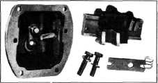
COVER AND SHIFTER
MECHANISM-DISASSEMBLY
1. Remove the two bolts which retain the guide
bar to the cover and remove the shifter forks and guide bar.
2. Remove the shifter yoke lever, anti-rattle
spring, operating shaft,
selector lever and bell crank,
Fig. 15. |
|||
 |
|||||
|
Fig. 13-lnstalling Mainshaft
shaft against the inner race of
the bearing may be determined by checking the end play of the second-speed
gear which should be approximately .010".
Clutch Gear
1. Using an arbor press, press the clutch gear
bearing onto the clutch gear
with the locating ring toward
the front end of the gear shaft so that the bearing will enter the case to the
maximum possible
depth.
2. Install the combination clutch gear bearing
retaining nut and oil slinger
on the clutch gear shaft and
draw it up tight, using the special wrench, J-933.
3. Lock the retaining nut and oil slinger in
place by staking it into the
hole with a center punch. Care
must be used not to damage the thread on the shaft. |
|||||
 |
|||||
|
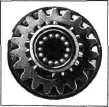
4. Place
some cup shaft pilot hole in
the clutch gear and install the 14 roller bearings, Fig. 14. After being assembled in the pilot hole, these bearings will lock themselves
in place and cannot fall out. Install the clutch gear in the transmission
case. |
grease in the main- |
||||
 |
|||||
|
Fig. 15—Transmission Shifter Cover
Assembly
3. Slide the shifter forks off the
guide bar, being careful not to lose the detent balls and
spring. |
|||||
|
Fig. 14—Mainshaft Pilot Bearing
Rollers in Clutch Gear |
|||||
|
|
|||||