|
ROCHESTER CARBURETORS Bulletin 9D-9 January 1952 |
|||||
|
Page 7 ROCHESTER
PRODUCTS, DIVISION OF GENERAL
MOTORS, ROCHESTER, NEW YORK |
|||||
|
|
|||||
|
POWER SYSTEM
|
|||||
|
|
|||||
|
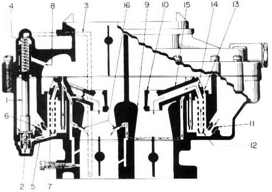
Figure 7-3 |
|||||
|
|
|||||
|
Use Figure 7-3 as a
reference.
To achieve the proper mixtures
required when more power is desirable or sustained high speed driving is
to be maintained the Model 4GC Carburetor employs the use of a vacuum
operated power piston (1) in the air horn and a power valve (2) in the
float bowl. This power system is located on the primary or pump side of
the carburetor.
The power piston vacuum channel
(3) is exposed to manifold
vacuum beneath the throttle valves. The vacuum in this channel varies
directly with the manifold vacuum. In the idling and part throttle
ranges, the manifold vacuum is normally quite high. This vacuum is
sufficient to hold the power piston (1) in its extreme up position.
However, as the throttle valves are progressively opened the manifold
vacuum drops. When the vacuum drops below approximately 7" Hg. the
calibrated spring (4) beneath the power piston forces the piston
down. This situation occurs at very high driving speeds or on rapid
accelerations. When the piston drops down, it unseats the spring loaded
power valve (2). This permits additional fuel to flow from the float bowl
through the calibrated power restrictions (5) and into the main wells. 1
his additional fuel supplements that already flowing through the main
metering jets (6) and main well tubes (7), (on the Primary side) thus
making the mixture being delivered to the manifold, consider-ably richer
than normal Part Throttle mixtures. This power mixture continues to be
supplied as long as the manifold vacuum remains below approximately 7" Hg.
When the manifold vacuum again increases sufficient-ly, the force of the
power piston spring (4) is overcome and the piston is drawn up, thus
returning the carburetor |
to the economical part
throttle mixtures.
It will be noted that the power
piston cavity in the carburetor air horn is connected to the main air flow
passage by a vacuum break hole (8). It is the purpose of this hole to
prevent the transfer of vacuum acting on the piston from acting also on
the top of the fuel in the float bowl. Any leakage of air past the upper
grooves of the piston will be compensated for by this vacuum break hole
and will not affect carburetor calibration.
It is also in this range that the
secondary side of the carburetor provides additional air and fuel to the
engine for increased power. For high speed operation, beyond the part
throttle range, the throttle linkages engage the secondary throttle valves
and open them completely in the remaining few degrees of primary throttle
travel.
In this range manifold vacuum or
suction, acting on the secondary side of the carburetor is multiplied at
the primary (9) and secondary (10) Venturi and draws fuel from the
float bowl through the calibrated main metering jets (11) into the main wells. This fuel
then passes through the main well tubes (12) and is bled in a manner similar
to that discussed previously in the operation of the Primary main well air
bleeds. This mixture is bled further at the main well bleeds (13) and is then drawn to the tips
of the main well tubes (14). It then passes through the mixture passage
(15) to the secondary Venturi
(10) and is discharged into the intake manifold.
The lower idle air bleeds (16) also supply fuel throughout the
power range in a manner similar to that discussed under the Part Throttle
System operation. |
||||
|
|
|||||

