|
ROCHESTER CARBURETORS Bulletin 9D-9 January 1952 |
|||
|
Page 8
ROCHESTER PRODUCTS, DIVISION OF GENERAL MOTORS,
ROCHESTER, NEW YORK |
|||
|
|
|||
|
ACCELERATING PUMP SYSTEM |
|||
|
|
|||
|
|
|||
|
|
|||
|
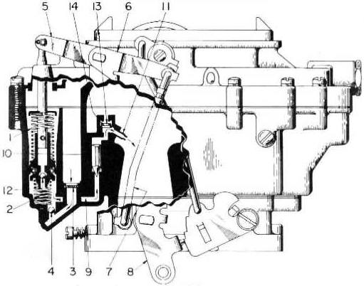
Figure 7-4 |
|||
|
|
|||
|
When the throttle is opened
rapidly the air flow and
manifold vacuum change almost instantaneously while the heavier fuel tends
to lag behind causing a momen-tary leanness. The accelerator pump provides
the fuel necessary for smooth
operation on rapid acceleration.
Use Figure
7-4 as a reference.
Since the throttle valves on the
secondary or fuel in-let side of the carburetor remain fully closed
throughout part throttle operation, it is only necessary to have
one accelerator pump, that being
located on the primary or
pump side of the carburetor.
A double spring pump plunger is
used on the Model 4GC Carburetor. The
rates of compression of the top spring (1) versus the bottom spring (2) are carefully calibrated to
insure a smooth, sustained charge of fuel for acceleration.
On the pump intake or up stroke
fuel from the float bowl passes through the pump filter screen (3), unseats the aluminum inlet ball
(4) and fills the pump well.
The accelerator pump, being
connected, through the inside pump lever (5). pump shaft, and lever
assembly (6) and pump rod (7). to the throttle lever (8) moves at the slightest change in
throttle opening. Upon acceleration or down stroke of the pump
plunger, the force of fuel in the pump well seals the inlet ball (4). The
fuel is then forced through the discharge channel (9) unseals the pump outlet needle (KM. and
discharges through the pump jets (11) into the main air stream. No targeting of these
pump jets is required. |
The Model
4GC Carburetor accelerator pump system is vented twice for peak operating
efficiency.
The pump plunger head has been
vented to minimize the effect of fuel percolation in the float bowl pump
well. This has been accomplished by
the design of a ball check and seat in the plunger head (12). In this manner any build up of fuel vapors in the pump
cylinder will rise and by-pass the ball, thus venting themselves
into the float bowl. There is,
therefore, always a charge of solid fuel beneath the plunger head for
rapid acceleration. Without this feature, any vapor pressure build up
would evacuate the charge of fuel in the pump system, thus causing poor initial
acceleration as well as difficult hot weather
starting,
The atmospheric vent valve is
located in the primary Venturi cluster (13) in the channel above the pump
discharge jets. Upon sudden
acceleration, the force of fuel past the outlet needle seats the
valve in its "up" position, thus
preventing a discharge of fuel through the vent passage. Under constant
throttle conditions, the weight of the valve causes it to rest
against its spring retainer
(14), thus permitting air to flow from the inside bore of
the air horn, through the vent
and into the chamber above the pump outlet needle. This vent valve
utilizes the suction at the pump jets by progressively increasing the
force tending to scat the outlet needle, with each increase in throttle
opening. This prevents a condition
known as pump pullover, or a discharge of fuel from the pump jets during high speed
operation. |
||
|
|
|||

