1942 - 1947 CHEVROLET SHOP MANUAL
Section 12 - Electrical System
|
|
|||
|
12-19
|
|||
|
|
|||
|
ground. This will
operate the generator as a motor.
The ammeter reading, with the generator running, should be from
4 to 6 amperes.
When motoring voltage regulated generators,
make sure to connect the positive
of the battery to the
positive terminal of the generator, otherwise
the residual magnetism of the
generator will be reversed,
thereby reversing the polarity of the
generator.
After overhauling a
voltage regulated generator, the
voltage setting and the generator output (amperage) should be
checked on the car or truck as described earlier in this section.
NOTE—It is good
practice, after reassembling a generator on the car or truck, to use a
juniper lead to momentarily connect the battery terminal of the
regulator with the generator terminal. This sends a current through
the generator windings, assuring that if will build up in the proper
polarity.
THE STARTING SYSTEM
The starting system has only one function to
perform—to crank the engine. In
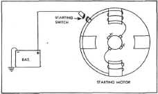
the starting system, there are three units: the battery, the starting
switch and the starting motor, Fig. 41.
|
THE STARTING MOTOR
The starting motor is similar in construction and appearance to the
generator, but the design of the
parts is different. Both motor and generator require
frame, field coils, armature, brushes, etc. The
operation of the starting motor is
the reverse of the
generator. In the case of the generator, a loop of
wire is revolved in the magnetic
field and generates current. In the case of a starting motor,
current is supplied to the loop
which lies in a magnetic field. As the loop rotates, mechanical energy
is produced.
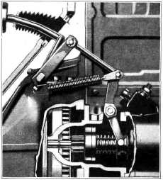
The starting motor is designed to incorporate a
manual shift drive mechanism
which assures positive
engagement of the starting motor pinion with
the flywheel until the engine is
started, Fig. 42. This is of particular benefit when starting a
cold engine, as the starting
motor will continue to crank
the engine as long the the driver
depresses the starter
pedal.
In this design, the starter pinion in conjunction
with an over-running clutch (or
roller clutch), a
compression spring and pulley-like sheave are
mounted as an assembly on the
splined part of the armature shaft. The sheave and spring are mounted
to rotate freely on the outer diameter of the tube portion of the
assembly. Fig. 42.
|
||
 |
|||
 |
|||
|
Fig. 41-Starting
Motor Circuit
The battery supplies the energy, the switch completes
the circuit, allowing this energy to flow to the starting
motor. The motor then delivers mechanical
energy and does the actual work of cranking the engine. The starting
equipment is used for a
short time only and then remains idle until it is
again needed to start the engine.
The battery, however,
performs other functions.
It should be noted that the starting motor draws
a large amount of current for a
short period of time,
whereas the generator replaces this current by
charging the battery at a lower
rate for a much longer
period of time.
|
|||
|
Fig. 42-Cut-Away View of Starting Motor Drive
A multiple spring and
roller over-running mechanism, Fig. 43, similar to that of a bicycle
coaster brake, is located between
the outer part of the
clutch which is attached to the pinion and the
inner part splined to the
armature shaft.
|
|||
|
|
|||