1942 - 1947 CHEVROLET SHOP MANUAL
Section 12 - Electrical System
|
|
|||
|
12-33
|
|||
|
|
|||
|
HEADLAMPS
The "Sealed Beam"
headlighting system is used on all passenger cars and trucks. These
lamps are designed so that the light source, the reflector, the lens
and the gasket are all assembled in one securely sealed unit, known
as the sealed beam unit. When the filament burns out or the lens
becomes damaged or broken, the entire sealed beam unit is thrown away
and a new one installed, thereby assuring maximum lighting efficiency
throughout the entire life of the car.
"Sealed Beam"
headlamps provide two separate and distinct beams, giving the maximum
amount of road illumination at all times.
1. A
country (upper) beam (bright lights) is
designed to illuminate the road
evenly for considerable
distance ahead of the car. This beam
is for use on the open highway
when no other vehicles are
approaching.
2. A
traffic (lower) beam is also provided and is
low enough on the left side to
avoid glare in the eyes of
the oncoming drivers. It is intended
for use on heavily traveled
highways and should always
be used well in advance of approaching
vehicles. This beam is designed
so that it does not throw
any dazzling light into the eyes of
the approaching driver under any
condition of car loading. At the same time the distribution
of light is such that the right
side of the road is
illuminated as far ahead as is practicable without causing glare on
curves.
The operation of the
headlights is simple, allowing the motorist to use either the country
(upper) or the traffic (lower) beam as traffic and road conditions
demand by the use of the conveniently located dimmer switch on the
left side of the toe-pan.
When the country
(upper) beams are lighted a red pilot bulb in the instrument cluster,
at the top of the speedometer, will be illuminated, making it
convenient for the driver to determine when the bright lights are on.
Never pass an approaching car with this red light burning. ALWAYS
SWITCH TO THE TRAFFIC
(LOWER) BEAM WELL IN
ADVANCE OF ONCOMING CARS.
LAMP CONSTRUCTION
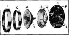
The sealed beam unit
(A) Fig. 69 is held to a sub-body
(B) by a retainer ring (C) and three screws which may be
loosened for removal of the unit. The sub-body forms a ball and socket
joint with a lamp housing (D) and is held to the housing by four coil
springs (E), plus the vertical adjustment screw (F), and the
horizontal adjust-
|
ment screw (G). With
this type of mounting the horizontal light beam adjustment can be made
without disturbing the vertical light beam setting and vice versa. The
sealed beam unit is provided with three locating lugs (H) which fit
into corresponding slots in the sub-body. These lugs are so located
that this unit can only be mounted in one position.
|
||
 |
|||
|
Fig. 69-Sealed Beam Headlamp Parts
With this system
maintenance is greatly simplified, requiring only aiming of the beams
and the replacement of burned out or broken sealed beam
units.
Neither dust nor moisture can get at the
reflector because the entire unit is
sealed. The units
|
|||
 |
|||
|
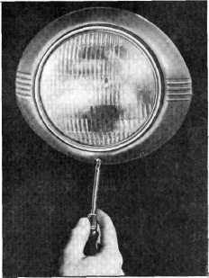
Fig. 70-Removing Headlamp Rim
|
|||
|
|
|||