1942 - 1947 CHEVROLET SHOP MANUAL
Section 12 - Electrical System
|
|
|||
|
12-34
|
|||
|
|
|||
|
in both the left and right hand headlamps are
identical and cannot be installed
improperly, nor can the electrical connections be attached in any but
the right way. The filaments are very accurately
prefocused in these units with respect to the reflector and
their position cannot be changed.
This feature makes it such that when replacing a
unit the new unit will take
substantially the same aim
as before.
|
with a light colored vertical screen 25 feet ahead.
For best road lighting results,
draw a horizontal line on
this surface at the level of a point 3" below
the headlamp center. If, however,
the State requires a loading allowance, draw this horizontal
line below the above mentioned
line, by the amount
required by the particular State. Sight through
the center of the rear window
over the center of the radiator ornament and so determine a
point on the horizontal line
midway between the headlamps.
Draw vertical lines through points
at the right and left of
this center point directly ahead of the center
of each headlamp. On cars equipped
with a divided
|
||
 |
|||
 |
|||
|
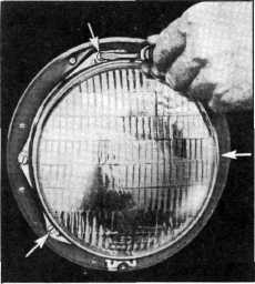
Fig. 71-Removing Headlamp Retaining Ring
Screws
TO REPLACE "SEALED BEAM" UNIT
1.
Remove headlamp rim, Fig.
70.
2. Remove
the three screws holding retaining ring,
Fig. 71. (Do not disturb aiming
screws.)
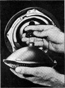
3. Remove
retaining ring by rotating counterclockwise,
allowing sealed beam unit to be removed.
4. Remove
connector plug from sealed beam unit.
Fig. 72.
5.
Install new sealed beam unit by
reversing above operations.
"SEALED BEAM"
HEADLAMP AIMING ADJUSTMENT
To obtain the maximum results in road illumination
and the safety that has been built into the headlighting equipment,
the headlamps must be
properly aimed. Place the car on a level stretch
|
|||
|
Fig. 72-Disconnecting Connector Plug
windshield, it is
necessary to locate a point on the
horizontal line by sighting past the left edge of the center
division and then past the right edge. A
point midway between these two
points represents the center line of the car on the screen from
which lines directly ahead of the
headlamp centers can be located. Figure 73 shows the
recommended headlamp aiming
chart with the left headlamp properly aimed.
Place the dimmer switch in the position which
produces the country (upper) beam
(bright light). When the
country (upper) beam is lighted the
lower filaments on both lamps are
illuminated.
|
|||
|
|
|||