1942 - 1947 CHEVROLET SHOP MANUAL
Section 4 - Rear Axle, Universal Joints & Springs
|
|
|||
|
4-14 |
|||
|
|
|||
|
Pinion
Disassembly
1. Clamp the rear yoke of the universal joint
in a bench vise and remove the
cotter pin, nut and washer from
the end of the pinion shaft.
The
universal joint rear yoke as well as the bearing retainer and oil seal may then be
removed from the pinion shaft.
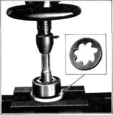
2. To remove the rear pinion bearing, take off
the lock ring and then using a
special press plate, J-1453.
press the pinion and shaft out of the bearing, Fig. 23.
NOTE—The raised portion of the
press plate must be against the inner race otherwise the bearing will be
damaged.
3. Install the front pinion bearing remover
J-1439 for 6 tooth pinion,
J-1440 for 7 tooth pinions, over the pinion teeth and against the inner
race of the double row pinion
bearing. Then press the bearing
off the pinion shaft, Fig. 24. |
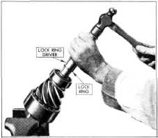
2. Press the rear bearing on the end of the
shaft with the chamfered side
of the inner race toward the
pinion. Install the lock ring using the lock ring installer J-1364, Fig.
25.
3. Slide the pinion bearing retainer and oil
seal over the universal joint
yoke. If replacement of the oil
seal is necessary, install the felt packing toward the bottom of the recess and
then the oil seal with the open
end of the leather toward the
pinion bearing. The oil seal should be pressed, down against the felt
packing, Fig. 15.
NOTE—Soak a new leather oil
seal in light engine oil for at least one hour before
installing. |
||
 |
|||
 |
|||
|
Fig. 25—Rear Pinion Bearing Lock Ring Installer
4. Install the pinion bearing retainer gasket
and then slide the universal
joint yoke over the splines on
the pinion shaft until it contacts the inner race of the
bearing.
5. Place the flat washer on the end of the
pinion shaft and tighten the
nut down to a torque load of 160 to 280 ft. lbs. Lock the nut in place
with the cotter
pin.
Differential Disassembly
The
differential side bearings are a press fit on each side of the differential. To remove
these bearings, the special puller shown in Fig. 26 should be
assembled to the case with the
two fingers of the puller in
the two notches of the case. This allows the fingers to pull in against the inner
race of the bearing which will
prevent damage to the bearing. These bearings should never be removed in an
arbor press because removing
them in this way will damage the bearings so that they will be unfit for
further use.
After the
bearings have been removed, they should be washed in gasoline or cleaning
solvent |
|||
|
Fig. 24—Removing Front Pinion Bearing
Inspection
Wash all parts in clean gasoline
or cleaning solvent. Inspect the pinion for worn or chipped teeth.
Inspect the splines on the pinion shaft for wear or scoring. Oil the bearings and turn them
slowly by hand to check for roughness. Check the fit of the bearings in the carrier. These should be a
close push fit by hand. Inspect the oil seal in the pinion bearing retainer and replace with a new one
if necessary.
Pinion Reassembly
1. Press
the front double-row pinion bearing onto the pinion shaft with the extended portion
of the bearing inner race
against the back of the gear teeth. |
|||
|
|
|||