1942 - 1947 CHEVROLET SHOP MANUAL
Section 4 - Rear Axle, Universal Joints & Springs
|
|
|||
|
4-16 |
|||
|
|
|||
|
1. Lubricate the differential side
gears and pinions and install them in
the left half of the differential case.
1.
Assemble the right side of the case to the left side, being sure to line up the marks on
the case halves, Fig.
27.
3. Install the guide pins. Slip the ring gear
over the pilot diameter of the
right-hand half of the differential case.
4. Install ten differential to ring gear bolts
and lockwashers, tightening
them evenly one turn at a time
until the ring gear face is flush with the case flange. Remove the guide pins and
install the two remaining
bolts and lockwashers. Then
pull up all twelve bolts tight.
5. Assemble the differential side bearings to
the case, using the special driver, J-1488.
NOTE—The wide side of the
inner race must be towards the case.
Differential Carrier Reassembly
1. Place the differential carrier in a vise
and install the bearing
cap dowels in the carrier or in
the bearing caps.
2. Assemble pinion assembly to the carrier
using new gaskets and tighten
the pinion bearing retainer bolts securely.
3. Install the differential assembly in the
carrier. Install the bearing
caps, making sure the marks on
the caps line up with marks in the carrier. Install the cap screws and tighten them
until |
the
lockwashers just flatten out. Screw the adjusting nuts into the carrier, making sure
they turn freely. Tighten them
snugly to straighten up the
bearing outer races.
4. Back
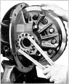
off the right-hand adjusting nut and tighten left-hand adjusting nut just to a
point where all lash between the ring gear and pinion is removed, Fig. 29. Then back off the
left-hand nut approximately two
notches and to locking position. Tighten right-hand nut to solid
position. Back off
right-hand nut free of bearing, then tighten up right-hand nut until all
play in bearing is removed and
then one to two notches more to
a locking position. |
||
 |
|||
 |
|||
|
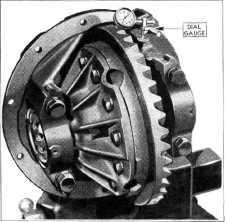
Fig. 30—Checking Ring Gear and Pinion Bach Lash
5. Check
ring gear and pinion back lash. This should be from .005"—.008". If it is more
than .008", loosen the
right-hand adjusting nut one notch and tighten left-hand nut one notch.
If less than .005", loosen the
left-hand nut one notch and
tighten the right-hand nut one notch. |
|||
 |
|||
|
|
|||
|
Fig. 29—Adjusting Ring Gear and Pinion Back
Lash |
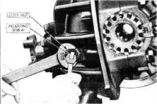
Fig. 31—Ring Gear Thrust Pad
Adjustment |
||
|
|
|||