1942 - 1947 CHEVROLET SHOP MANUAL
Section 6 - Engine
|
|
|||
|
6-41 |
|||
|
|
|||
 |
|||
|
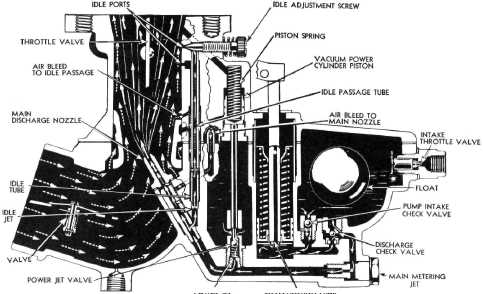
POWER JET
ACCELERATING PUMP
Fig.. 83—Diagrammatic View of Up-Draft C.O.E.
Carburetor |
|||
|
|
|||
|
in the choke valve and mixed with
gasoline drawn from the main nozzle,
forming a rich mixture for easy starting. Fig. 84. When the engine
starts, the auxiliary air valve
located at the center of the choke valve opens, admitting additional air
and prevents over-choking, Fig. 84.
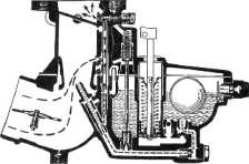
Idling
At idling
speed, air is drawn in through the idling air passage and passes between the
idle passage tube and the
carburetor casting to the end of the tube: here it passes over the idle jet
drawing gasoline from it. The
gasoline and air are mixed |
while
passing up the idle passage tube and discharged into the manifold through the idle
port. This operation is
illustrated in Fig. 85.
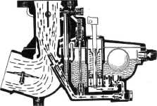
Accelerating Pump
As the
throttle is closed the accelerating pump piston is drawn upward, compressing the
spring. This results in gasoline flowing from the float chamber through the intake check valve into
the pump cylinder. Fig. 86.
When the
throttle is opened quickly the piston rod and plate are forced down the cylinder,
allowing the spring
tension on the piston to force the |
||
|
|
|||
 |
 |
||
|
|
|||
|
Fig. 85—Air Drawing Gas from Idle Jet |
Fig. 86—Accelerating Pump Action |
||
|
|
|||