1942 - 1947 CHEVROLET SHOP MANUAL
Section 10 - Wheels & Tires
|
|
|||
|
10-5
|
|||
|
|
|||
|
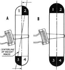
To correct this condition we must add weight to
sections 1 and 4, so they will be
equal to the weight of
sections 2 and 3. Notice that this addition
of weight now distributes the total weight
evenly about both the axis of
rotation and the center
line of the wheel as seen in Fig. 10-B. There-
|
 |
||
 |
|||
|
|
|||
|
Fig. 10-Wheel In Static and Dynamic Balance
fore, this wheel is now both statically and dynamically
balanced.
Wheels must be both statically and dynamically
balanced to give maximum steering
ease and stability at
speeds where unbalance becomes noticeable.
The wheels must be statically
balanced before they can be balanced dynamically. To
demonstrate the balancing of a
wheel assembly we will use a combination
static and dynamic wheel balancer, as
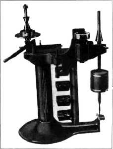
shown in Fig. 11.
Before the wheel assembly is balanced, the
wheel and tire must be clean and
free from all foreign
matter. The tires should be in good condition
and properly mounted, with the balance
mark on the tire lined up with
the valve stem in the
tube. Bent wheels that have a run-out of over 3/16"
should either be replaced or straightened before
being balanced.
CHECKING FOR STATIC BALANCE
The static balancer operates on the principle of
the pendulum and lever arm. The
pendulum is mounted free
to pivot, as shown in Fig. 11. An extension of the pendulum
rod with suitable cones forms an
arbor for the wheel which is to be balanced. Any unbalanced weight on
the wheel assembly when
mounted on the arbor acts through
|
Fig. 11 -Dynamic Wheel Balancer
|
||
|
the wheel as a lever arm and tends to move the
pendulum off center. The amount
of movement depends upon
the amount of unbalanced weight,
and is indicated on the scale
below by the pendulum pointer. Before placing a wheel on a static
balancer, be sure that the pendulum pointer falls
directly over the center mark on
the scale. If it does not,
the scale may be moved slightly to either
side to compensate. To static
balance a front wheel,
place the wheel on the static arbor with
the brake drum up. Using the
regular wheel bearings
between the special balancing cones, tighten
the arbor nut (with fingers)
sufficient to remove play and so that the wheel rotates easily.
When placed in a horizontal position, as in this
test, every wheel and tire
assembly will have a place
where it balances statically. Obviously, this place will be
through the center of the heavy section
of the wheel. Therefore, with the wheel in
position on the arbor, turn the
wheel slowly until in balanced position (balanced position is
determined when the pointer on
the pendulum rests
directly over the center line of the scale). Now
place the adjusting rod
(furnished with the machine)
on the arbor so that the mark "1" is directly in line with the mark
stamped on the end of the arbor. Now raise or lower the counterweight
by turning right or left until the pointer on
|
|||
|
|
|||