1942 - 1947 CHEVROLET SHOP MANUAL
Section 10 - Wheels & Tires
|
|
|||
|
10-6
|
|||
|
|
|||
|
the pendulum swings over the line between the
"poor" and "danger" zones. The
adjusting rod and weight
are used in connection with each other to calibrate the
sensitivity of the machine.
NOTE-The machine
should be calibrated each time a different wheel is balanced.
When the adjusting rod is removed from the arbor, the pointer should
return over the center line. If
it does not, turn the wheel a few inches in
either direction until the pointer
is directly over the
center line. With the pendulum weight properly
calibrated, we are now ready to balance the
wheel.
Replace the adjusting rod on arbor with mark
"1" directly in line with mark on
end of arbor and then chalk
the tire directly below the rod. Without moving the wheel, turn the
adjusting rod so that mark
"2" is directly in line with the mark
on the arbor, and again chalk the
tire directly below the rod. Again, turn the adjusting rod 90°
to the third position and make a
third chalk mark on the
tire. Repeat this operation and make a
fourth chalk mark on the tire.
Now, with the adjusting rod still on the arbor with one of the marks
lined up with the mark on the arbor, turn the wheel assembly 90c
(1/4 turn) and then remove the
adjusting rod. Indicator
pointer at bottom of pendulum will now show condition of the static
balance of the wheel assembly.
Place necessary weight (or
weights) on rim of wheel at chalk mark on right (or high) side of
wheel until pointer
returns to center line. If two
weights are required, they should
be placed at equal distances from chalk mark. When proper
weight has been determined, fasten
securely to rim of wheel.
After the wheel assembly has been statically
balanced, it should be rotated in
short steps, making a
complete turn to determine whether the
assembly is now balanced
statically in all positions.
CHECKING FOR DYNAMIC BALANCE
A dynamic balancer is composed of the dynamic
arbor and leveling plate assembly. The
leveling plate assembly is in turn
composed of the floating
spindle integral with the ball which forms
the leveling plate seat, the
leveling plate and the
mounting cones. (See Fig. 12.) In operation the
leveling plate assembly floats
free of the dynamic arbor so that any wobble in the wheel will
be shown. The leveling plate is a
snug fit on its ball seat
so that it rotates with the wheel, but may be tilted up or down
in relation to the spindle.
After the wheel assembly has been statically
balanced, it is ready for dynamic
balancing. With the wheel
bearings in place, lower the wheel as-
|
 |
||
|
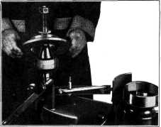
Fig. 12-Installing Leveling Plate
sembly onto the dynamic spindle with the brake
drum down. Place the small cone
over the spindle and adjust the nut snugly so the spindle will rotate
with the wheel and not
turn separately. Adjust
motor height so that the drive pulley contacts the
center of the tire; start motor
and revolve wheel for 20
or 30 seconds, after which the motor can be
switched off and the pulley
released from contact with the tire.
When a wheel revolves
at high speed on a floating
spindle, any uneven weight distribution will
cause the wheel and floating
spindle to change its axis of rotation so that the center line
of the weight mass becomes horizontal-or perpendicular-in relation
to the dynamic arbor, just as the weight on the string became
perpendicular in relation to the
hand.
With the wheel still revolving at high speed,
carefully raise the leveling
handle until the fibre button contacts the leveling plate continuously
and the plate runs true.
Then lower the leveling handle
and apply the brake to the tire
in order to bring the wheel
to a complete stop. When leveled in this manner, the leveling plate is
brought into parallel with the center line of the wheel mass, but not
necessarily in parallel to
the wheel itself because if the wheel was dynamically out of
balance, the wheel and leveled
plate are not in parallel.
Raise the indicator hub carefully into the arbor
socket, lifting it as far as
possible and holding it
there firmly. This operation brings the wheel
into perpendicular with the
dynamic arbor, and at the
same time tilts the leveling plate so that it now
has the same tilt or wobble that
was formerly in the
spinning wheel. Thus, when a reading is taken
from the leveling plate, it will
show the amount and
location of the dynamic unbalance in the
wheel.
|
|||
|
|
|||