1942 - 1947 CHEVROLET SHOP MANUAL
Section 3 - Front Suspension, Axle & Springs
|
|
|||
|
Section
3 |
|||
|
|
|||
|
KNEE ACTION OR INDEPENDENT FRONT WHEEL
SUSPENSION
PASSENGER CAR MODELS |
|||
|
|
|||
|
CONSTRUCTION
The 1942 passenger car front
wheels are independently sprung
by the S. L. A. (short and long arms) method.
This
design allows the wheel to move straight up or down in following irregularities of
the road. Whether these irregularities be raised obstructions or chuck holes, the shock will not be
transmitted to the car or
passengers.
In this
construction the complete assembly is attached to an unusually large and rugged
frame front cross member of
box section construction which
is rigidly bolted to the frame side rails, Fig. 1. This cross member is also
reinforced by a bracket under
each side rail. The brackets are riveted to the cross member and bolted to
the frame side rails. This construction facilitates complete overhaul or replacement in that the
complete assembly may be
removed from the frame as a unit.
Chassis
coil springs 14-1/8" long are employed which are mounted in seats, one seat
attached to the lower control arms and the other being in the frame front cross
member.
Double
acting shock absorbers of the parallel cylinder type are rigidly bolted to the top
of the frame front cross
member. The front and rear upper control arms are permanently attached
to the shock absorber shaft to
provide great strength and resistance to shock. The two upper arms
are electrically welded together.
Each lower control arm is pivoted at its inner end on a forged
shaft attached to the underside of the frame front cross member by two brackets forged integral with
the shaft (see Fig- 10). Each
control arm carries a hardened steel bushing of the thread bearing
type. Neoprene seals cover the inner
end of each bushing and the
threads on the shaft. These seals prevent dirt and water from
entering the bearings, thereby prolonging their life.
The
steering knuckle support, which carries the steering knuckle and kingpin, is pivoted at
its upper and lower ends to the upper and lower control arms.
At the lower end a steel threaded type bushing is screwed into the
steering knuckle support. A
threaded bolt which passes through both arms and the bushing completes the
mounting. Neoprene seals
protect the bearing from road dirt |
and water.
The upper end of the knuckle support is mounted to the upper control arms through
threaded bushings and a
threaded eccentric bolt which
provides for caster and camber adjustments.
The
steering knuckle is of the reverse Elliott type, pivoting on the kingpin through
floating bushings which permit
movement of the bushings on
the kingpin as well as in the steering knuckle. Two tie rods are
used which connect directly to the
pitman arm—the right-hand tie rod is solid while the left tie rod is adjustable to
provide for toe-in
adjustment.
Rubber
bumpers for rebound and compression are mounted on the frame front cross member
and lower spring seats. The lower (or compression) bumper engages the underside of the front
cross member and the upper (or
rebound) bumper engages
the upper support arm at the point where the two arms are welded
together.
A front-end stabilizer is used in
connection with this suspension to
provide steering stability and control of body roll. The stabilizer is a
long steel bar attached to the
under side of the frame side rails ahead of the cross member by
rubber bushed brackets. Delco type
connector links are used to connect the stabilizer bar to the coil
spring seats on the lower control arms. The linkage provides complete rubber insulation between the
metal parts. |
||
|
DUST COVER
PACKING |
|||
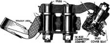
FORGED PLATE RUBBER
BUSHINGS |
|||
|
RETAINER PLATE
Fig. 2—Pitman Arm and Ball
and Socket Joint Assembly
The ball
and socket joints on the tie rod connections are of the self adjusting type,
protected from dirt and water by a dust cover and packing. This construction is shown in Fig. 2 at the
end that connects to the
pitman arm and in Fig. 17 at the tie rod end.
The pitman
arm is a built-up assembly (Fig. 2).
The pitman arm proper is a heavy forging machined to receive tapered rubber bushings.
The |
|||
|
|
|||