1942 - 1947 CHEVROLET SHOP MANUAL
Section 3 - Front Suspension, Axle & Springs
|
|
|||
|
3-5 |
|||
|
|
|||
|
Reassembly
When
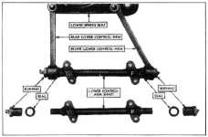
installing a lower control arm shaft, make sure that the bracket which has
the letter "F" forged in it is installed toward the front of the car as shown in Fig. 10. If this is not done the
bolt holes will not line up
properly. 1. Install a new
Neoprene seal on each end of the shaft which has a recess at the shoulders
conforming to the shape of
the seal, Fig. 10. Then install
the lower control arm shaft assembly shaft in the lower control arm assembly by
reversing the procedure
outlined under paragraph 4
of ''Disassembly". Be sure the shaft bracket with the letter "F" on it is toward
the front of the car. |
UPPER CONTROL ARM PIVOT PIN
Disassembly
1. Raise the car with a chain hoist, placing a
stand jack under the spring
seat, allowing jack to take
weight of the car. Remove wheel and tire assembly.
2. Remove the rear threaded bushing, (the upper
control arm and pivot pin
assembly is shown in Fig. 11
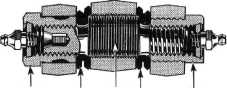
and a cross section through the pivot pin is shown in Fig. 12) then
remove |
||
 |
|||
 |
|||
|
FRONT
SEAL
PIVOT SEAL
REAR
BUSHING
PIN
BUSHING
Fig. 12—Cross Section of Upper
Control Arm Assembly
the clamp
bolt on the front upper control arm and remove the front
bushing.
3. Loosen
the clamp bolt at the upper end of the knuckle support and unscrew the upper pivot
pin, using a 1/4" Allen set
screw wrench.
Reassembly
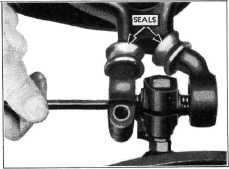
1. Using a
stiff wire hook, place a new Neoprene seal over the end of each upper
control arm in the position shown in
Figure 13. |
|||
|
Fig, 10—Layout of Lower Control Arm Parts
2. Install the lower control arm shaft
bushings, being certain to
centralize the shaft in the yoke formed by the lower control
arms.
3. Install the lower control arm assembly to
the car by replacing the lower control arm pivot pin in accordance with instructions given.
Then complete the assembly in
accordance with instructions given for replacing the front
spring. |
|||
 |
|||
 |
|||
|
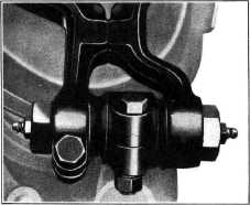
Fig. 13—Centering Pivot Pin in Knuckle Support
Assembly
While
holding the knuckle support between the yoke formed by the upper control
arms, use an Allen set screw wrench to
screw the pivot pin into the
support making sure the hole
for the Allen wrench is toward the front of car. Turn the pivot pin until the bolt
section with the largest
diameter is centered in the knuckle support, Fig. 13. Tighten clamp
bolt at upper end of the
knuckle support. |
|||
|
Fig. 11—Upper Control Arm and Pivot Pin
Assembly |
|||
|
|
|||