1942 - 1947 CHEVROLET SHOP MANUAL
Section 3 - Front Suspension, Axle & Springs
|
|
||||
|
3-4 |
||||
|
|
||||
|
4. Continue to screw the pivot pin
until it contacts the rear lower
control arm. Proceed carefully
at this point. If the threads on the pin and in the control arm
index properly, continue to screw the pin into the control
arm |
may be slipped off the rear end of
the bushing with the fingers. This method of installing the seals prevents
any possibility of damaging them during assembly operations.
LOWER CONTROL ARM SHAFT
Disassembly
1. Disconnect the stabilizer link from the
lower spring seat and perform the operations for removing the front spring, as previously
described in this
section.
NOTE—As a matter of safety, it
is good policy to place a stand jack under the front cross member while
proceeding with this operation.
2. Remove the lower control arm pivot pin. This
frees the entire lower control
arm assembly from the car so
that it may be taken to the bench for further
operations.
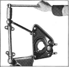
3. Place the lower control arm and spring seat
assembly in a vise and remove
the front and rear lower
control arm shaft bushings, Fig. 9. |
|||
 |
||||
|
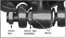
Fig. 6—Position of Neoprene Seals Before Installing Pivot
Pin
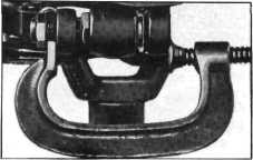
until its
head seats firmly against the front lower control arm. However, if the threads
do not index, and the control
arms are being spread by the
pivot pin, place a "C" clamp |
||||
|
|
||||
 |
 |
|||
|
Fig. 7—Indexing Threads on Lower Pivot Pin and Rear
Arm
on the
control arms and compress the arms |
||||
|
slightly,
trying the threads as you
proceed, Fig. 7. It will
be found that very
little compression will
allow the threads to index
properly without spreading
the arms or binding the pivot
pin.
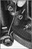
5. With a
hook made of stiff wire, slip the
front Neoprene seal
around the end of control arm and into
|
 |
|||
|
Fig. 9—Removing Lower Control Arm Shaft
Bushings
4. Then shift the lower control arm shaft
assembly as far as possible toward the bushing hole in either lower control arm, this will
allow the opposite end of the
shaft assembly to clear the hole in the other arm. The lower control arm
shaft assembly can now be
removed from the assembly.
5. While the lower control arm shaft and
bracket assembly is removed, it
is good policy to check the
rivets holding the front and rear control arms to the spring seat for
looseness. |
||||
|
its seat, Fig. 8. The rear
Neoprene seal |
Fig. 8—Positioning Neoprene
Seal at Lower Pivot Pin |
|||
|
|
||||