1942 - 1947 CHEVROLET SHOP MANUAL
Section 3 - Front Suspension, Axle & Springs
|
|
|||
|
3-8 |
|||
|
|
|||
|
less than 3/32" op more than 1/4",
parts responsible (knuckle arm, pitman arm, short tie rod ends or
long tie rod) must be replaced as necessary to bring this space within the
limits, 3/32" to 1/4". Wear on the tapered section of the ball stud
or hole in arm to decrease this space below 3/32" could only
be caused by running a considerable period with the ball stud nut
loose.
FRONT SUSPENSION ALIGNMENT
Front
suspension alignment is the mechanics of adjusting all the inter-related factors,
such as caster, camber, and
toe-in, etc., affecting steering. Incorrect adjustment of these factors may
result in hard steering, car
wander, shimmy, and abnormal tire wear. Complete information on
front wheel alignment
principles as well as the importance of each angle and adjustment is given later in
this section.
PRELIMINARY INSPECTIONS
Before checking the alignment of
the front suspension inspect the following, making necessary
adjustments or corrections:
1. TIRE MOUNTING-Check rim run-out and
eccentricity.
2. TIRE PRESSURE—Check and set to
recommended pressures for
the tires being used.
3. FRONT WHEEL BEARINGS-Check
for
looseness.
4. KINGPIN BUSHINGS-Check for
looseness.
5. STEERING GEAR-Check mounting bolts for
tightness.
6. STEERING CONNECTIONS-Inspect ball
and socket joints for
tightness.
After completing the above and
making any necessary adjustments, the front suspension
may |
be checked
on any reputable front end alignment
equipment.
In discussing the checking and
correction of alignment in this Shop Manual, we have selected for
illustrative purposes equipment that is in general use.
When placing the car on the front
end machine be sure that the front wheels are centered on the turntables
and that the front and rear wheels are parallel to the sides of the
runways. The rear wheels should be blocked to make certain the car will
not shift its position.
The front suspension is built as a
unit which includes the front cross member. The alignment of this unit is
adjusted at the factory with a fixed load applied to the assembly which
results in a given height from the top of the cross member to the center
line of the spindle. This is equivalent to a certain frame height when the
assembly is installed on the car.
The alignment specifications are
based on this normal frame height. Therefore, it is necessary that the
frame height at the front be set in this normal position in order to
duplicate the ORIGINAL FACTORY
SETTING CONDITIONS.
The alignment will vary with
different loads and operating conditions, but when set as above the
variation in caster, camber and toe-in will be within limits
necessary for satisfactory operation.
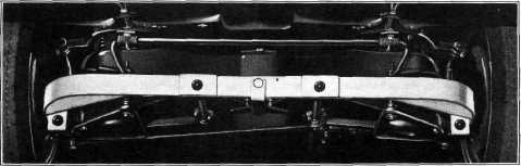
To locate the frame to the proper
height, install the approved gauge on the front. When installing the
height gauge, place the two center holes of the gauge over the lower
support arm shaft bushings; then raise or lower the front of the car by
the bumper until the sockets in the ends of the gauge fit over the hex
head of the lower pivot pins. Then install the clamp which locks the gauge
to the front cross member, Fig. 18. |
||
|
|
|||
 |
|||
|
|
|||
|
Fig. 18—Position of Height Gauge at Front of
Car |
|||
|
|
|||