1942 - 1947 CHEVROLET SHOP MANUAL
Section 3 - Front Suspension, Axle & Springs
|
|
|||
|
3-15 |
|||
|
|
|||
|
constantly in mind to gain a full
and true understanding of this
cleverly designed mechanism. In order to correct any wrong adjustment, it
is necessary to realize what effect a change in one element
of the mechanism may have on
the operation of the other
parts.
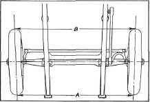
TOE-IN
Toe-in is
the amount in fractions of an inch that the wheels toe-in, that is, the distance
between the wheels at the front "A," is less than it is at the rear
"B," Fig.
34. |
 |
||
|
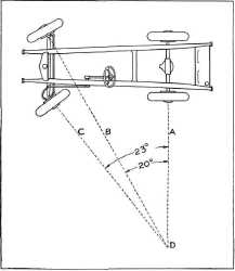
Fig. 35—Steering Geometry
The
accuracy of the steering geometry is governed by the condition of the steering
arms. For example, suppose a steering arm has been bent by bumping against a curb in such a way as to
cause the right wheel to toe-in
excessively when the car was turned around a corner. This tire would drag,
causing rapid wear of that
tire. The condition accounts
for the cars and trucks we see once in a while that wear out one front tire twice as
fast as the other, although,
by usual tests, it is perfectly set for straight ahead
driving. |
|||
 |
|||
 |
|||
|
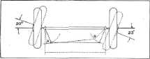
Fig. 34—Toe-In
Cambering
the wheels out at the top makes it necessary to draw them in at the
front.
Toe-in is a necessity growing out
of camber and directly related to it.
It might seem that since the
wheels are headed inward toward the center of the road, while
actually traveling a parallel course, there must be a constant grinding of their
surfaces on the road surface. It would appear that they are being held apart constantly by the axle,
against their tendency to roll outward to the same point. As a
matter of fact, it is to avoid this tire-wearing surface grind that toe-in is
employed.
Just as
the purpose of camber is to give the wheel a setting so it will be in nearly a
balanced free-running position
as possible, so with toe-in, the purpose is to set the wheel in a
position to reduce to a minimum
the road friction on the tire.
STEERING GEOMETRY
Steering
geometry is the mechanics of keeping the front wheels in proper relative
alignment as the wheels are
turned left or right, Fig. 35.
The front
wheels, when the truck is making a turn, are not on the same radius line, drawn
from the center around which
the truck is turning, and because of this, it is necessary for the front
wheels to assume a toed-out
position when rounding curves.
This position is governed by the angle of the steering
arms. |
|||
|
Fig. 36—Toe-Out on Curves |
|||
|
The wheel of any vehicle, if
properly set on the curves, will be at
a right angle to the radius line from the center or point around which the
vehicle is
turning.
Fig. 36 is
a diagram of a truck making a left turn. The right wheel is set at an angle of
twenty degrees—the angle being exaggerated to bring out the principles more clearly. A line "A"
drawn through the rear axle
and both rear wheels and a line
"B" drawn through the spindle of the right wheel meet at "D," which is the center
around which the car is
turning. Therefore, the left or |
|||
|
|
|||