1942 - 1947 CHEVROLET SHOP MANUAL
Section 3 - Front Suspension, Axle & Springs
|
|
|||
|
3-16 |
|||
|
|
|||
|
inside
wheel must be at right angles to the radius line "C" which passes through the spindle
and strikes the lines from the
other three wheels at "D."
REPAIR OPERATIONS
When
service men thoroughly understand the foregoing, they will appreciate the accuracy
necessary when checking
the front end system. There are
several different kinds of equipment, by which these operations can
be performed.
It must be
remembered that no matter what kind of
equipment is used, that all of these checks must be made with the truck level, with the
weight of the truck on the
wheels and with no pay load.
Bad
steering performance may be due to some cause not connected with front wheel
alignment. Therefore, check to
see that none of the following conditions are present before placing the
car on the front end
machine:
1. Loose or improperly adjusted steering
gear.
2. Steering housing loose at
frame.
3. Play or excessive wear in kingpins or
bushings.
4. Loose tie rod or steering
connections.
5. Loose spring shackles.
6. Loose front spring "U"
bolts.
7. Front spring slipped on spring seat due to
sheared center
bolt.
8. Over lubricated front
springs.
9. Sagging or broken front
springs.
10. Under inflated tires.
11. Unbalanced or improperly mounted
tires.
12. Motor mountings improperly
adjusted.
13. Broken motor mountings.
14. Motor not properly tuned, rough or
"missing."
15. Brakes dragging.
16. Hub bolt nuts loose.
17. Shock absorbers not operating properly, low
on fluid or dry.
After this inspection is completed
and the conditions corrected, the truck should be placed on the front
end machine and checked. There are several types of front end machines on the market
using different mechanical means for locating and correcting front end troubles. The instructions
furnished by each
manufacturer for the operation of his particular machine should be followed.
However, for the benefit
of those service men who do not have access to any of the various front
end machines, we shall explain the checking and correcting of
front end alignment with the use of the "Jiffy" Wheel Aligning
System. |
CHECKING FRONT END ALIGNMENT
Before any front end alignment
checks are made, the first thing that
should be done is to make sure that the truck is on a level floor and that
all tires are inflated to the proper pressure. Then, after making
the foregoing preliminary inspections, proceed to check the front end
alignment. |
||
 |
|||
|
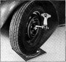
Fig. 37—Checking Kingpin Caster
CASTER CHECK
1. Set the front wheels in a straight ahead
position on the
turntables with the turntable scale set at zero. Install the "Jiffy" gauge,
J-800-A, parallel with the
spindle.
2. Turn the wheel on which the check is being
made OUT 25°, center the bubble on the gauge and note the reading on the Caster Scale,
Fig.
37.
3. Now turn the wheel IN 25°, center the
bubble and note the reading on
the caster scale. The caster of
the wheel is the amount in degrees of pointer travel from left to right from the
first reading. Should the
pointer travel from right to
left, reverse caster is indicated.
CAMBER CHECK
1. Set the wheels in a straight ahead position
and install the "Jiffy" gauge
parallel with the spindle as
shown in Fig. 38.
2. Adjust the gauge until the bubble in the
level is centered and read the amount of camber on the scale. Camber is
shown to the left of zero on
the scale, reverse camber being indicated if the pointer is to the right of the zero
mark on the
scale. |
|||
|
|
|||