1942 - 1947 CHEVROLET SHOP MANUAL
Section 3 - Front Suspension, Axle & Springs
|
|
|||
|
3-21 |
|||
|
|
|||
|
plate assembly should be wired
up to the sub-frame, Fig. 45.
The
steering knuckle may now be removed by
disconnecting the
steering connecting rod from the
steering
arm. Then remove the nut from the steer-
. ing arm
and drive the arm out of the knuckle,
using a
"knock-out" to protect the threads. |
steel
thrust washer, and install it on the kingpin between the "I" beam and the upper yoke of
the knuckle. Then push the
kingpin through the "I" beam, thrust bearing, and lower
yoke.
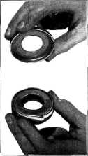
The
steering knuckle thrust bearing is of the roller bearing type and has a removable
shield, Fig.
47.
This shield
should be installed on the open side of the bearing, and when assembling on the
kingpin it must be on top
of the thrust bearing with the
flange side down.
Complete
the assembly by installing the kingpin lock pin from the rear of the "I" beam and
then upset the edge of the
hole around the large diameter of the lock pin with a center punch to
retain the pin in place. Install the packing, retainer, and snap ring on the top of the kingpin and
drive in a new bottom kingpin
bearing plug. The edge of the steering knuckle around the bottom plug
should be upset or peened over
to hold the plug in place properly. Assemble the steering arm to the
knuckle and assemble the
steering connecting rod, brake flange plate, and wheel hub
assembly.
Trucks that
have been operated for a period of time with loose kingpin bushings, in many
cases, tend to "bell mouth" the kingpin holes in the ends of the "I" beam. As a means of making a
satisfactory repair and
prevent future kingpin breakage due to the kingpins being loose in the "I"
beam, .010" and .020" oversize kingpins and bushings have been released for Conventional
Heavy-Duty 1-1/2-Ton Trucks.
Special
reamers are available on the market for reaming the holes in the "I" beam ends for
oversize
kingpins.
KINGPIN FLOATING BUSHINGS
1/2 AND ALL 3/4-TON MODELS
On the
1/2 and all 3/4-ton trucks the kingpin bushings are bronze bushings of the
"floating" type. When replacing these bushings it is not necessary to ream them to size, as service
bushings are machined to
finished dimensions. However, when replacing floating bushings care
should be used to make sure
that the oil groove in the bushing lines up with the lubrication
fitting in the steering
knuckle. These bushings should be free on the kingpin, but may be somewhat snug in
the steering
knuckle.
After the
kingpin bushings have been installed, the front end alignment should be checked
to make sure that all of the
factors of front end alignment are within the specified
limits. |
||
 |
|||
|
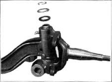
Fig. 46—C.O.E. Kingpin Retainer Parts
Remove the kingpin by removing the
snap ring, retainer, and packing from
the top of the kingpin, Fig.
46. Drive out the kingpin lock pin from the front of the "I" beam.
By driving downward on the kingpin it may be removed along with the bottom
bearing plug. This disconnects the steering knuckle from the "I" beam.
When
reassembling the kingpin, thread it through the upper yoke of the knuckle,
grease the |
|||
 |
|||
|
Fig. 47—C.O.E. Steering Knuckle Thrust
Bearing |
|||
|
|
|||