1942 - 1947 CHEVROLET SHOP MANUAL
Section 3 - Front Suspension, Axle & Springs
|
|
|||
|
3-20 |
|||
|
|
|||
|
To remove
the stabilizer from the truck, first remove the spring "U" bolts attaching it to
the top of the spring and then
remove the large bolt at the
upper end of the two-piece bracket which extends through the bracket, spacer, and
frame side rail. The
stabilizer assembly can then be taken from the car. To remove the bracket from the
bar it is necessary to remove
the bolts holding the two-piece
bracket together so as to relieve the pressure on the rubber bushings. The bracket and
bushing can then be slipped
off over the end of the bar.
Replacing
the stabilizer on the truck is the reverse of the above, except that the bolts
which clamp the two parts of
the bracket together should not be tightened until after the stabilizer
is in place on the truck, and
the weight of the truck with no pay load on its wheels. This is important so
that the rubber bushings will
grip the bar in proper relation to the frame and axle, and prevent
excessive up and down
movement of one front wheel relative to the other.
CAUTION-Do not attempt to
adjust the stabilizer by tightening the bolts in the bracket when
there is a load in the truck. This would destroy its
effectiveness.
All commercial frame front cross
members are punched for the adaptation
of this assembly if desired.
REMOVING AND INSTALLING
KINGPIN
To remove
and replace the kingpin, jack up the
front of the truck and remove the front wheel. Remove the nuts which attach the brake
flange plate to the steering
knuckle. Remove the brake flange plate. Remove the top kingpin
bearing plug. This can be done
with a sharp prick punch. Remove the kingpin lock
pin.
Drive the
kingpin down and out of the bottom with a brass rod. This removes the bottom
plug and the
kingpin. |
In
replacing the kingpin the operations are just the reverse of the above removal operations,
except that you should always use new kingpin bearing plugs and new
lock washers, and clinch over all cotter pins securely.
The kingpin bearing plugs on all
trucks except at the top of the kingpins on C.O.E, models, have no "expansion" feature, and must be staked in
place by peening or staking over the ends of the steering knuckle to hold the plugs securely in
place.
Drive in
the kingpin with a soft head hammer. After the kingpin is installed with the
thrust bearing assembled
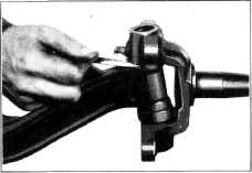
at the bottom of the kingpin with the dust shield side at the top, check the
clearance between the steering
knuckle and axle "I" beam, Fig. 44. If this clearance is more than
.006" install a steel shim between the steering knuckle and the "I" beam at the top of the
kingpin.
In
installing this shim, start the kingpin in at the top of the knuckle and place the shim
over the kingpin. Mount the knuckle over the end of the "I" beam and drive the kingpin part way
through the "I" beam. Insert
bearing between the "I" beam and the knuckle and drive the kingpin into
position.
Due to the difference in design
between the Cab-Over-Engine and the conventional truck front axle, kingpin replacement is slightly different on
the C.O.E., and should be performed as follows after raising the
front end of the truck and removing the wheel and hub.
Remove the
turning radius stop bolt to provide wrench clearance. Remove the four brake
flange plate to steering
knuckle bolts and remove the flange plate
assembly. |
||
 |
|||
 |
|||
|
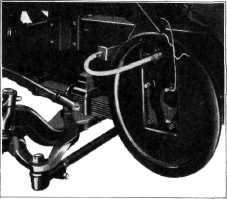
Fig. 45-C.O.E. Brake Flange
Plate Wired Up to Protect Brake Hose
NOTE—In order to protect the
brake hose while performing the following operations, the
flange |
|||
|
Fig. 44—Clearance Between Steering Knuckle and "I"
Beam |
|||
|
|
|||