1942 - 1947 CHEVROLET SHOP MANUAL
Section 3 - Front Suspension, Axle & Springs
|
|
|||
|
3-19 |
|||
|
|
|||
|
driven out
by inserting a bar through the hub so that one end rests against the cup. By
tapping lightly at several
points around the circumference of the cup, through notches in shoulder
inside of hub, it can be removed without damage. It is well to remember that the cups are very hard,
therefore, extreme care
should be used in removing not to crack them.
In
replacing the cups, be sure that they are pressed into the hubs evenly and
as far as they will go, that is, that
their backs are against the shoulder in the bottom of the
hole.
Before
installing the separator and ball assemblies in the hub they should be packed with
grease. Use a high melting point front wheel bearing grease on all passenger cars and conventional
trucks, and a soft smooth
grease on C.O.E, models. (Fibrous or viscous type lubricants must not be used.)
DO NOT put grease into the
hubs, as such excess grease is
not required and simply increases the chances of leakage into the brakes.
CAUTION—The necessity of
removing the bearing cups is usually due to damage to the
ball race in the cups,
in which event, the only, remedy is a new
part.
When
replacing the front wheel be sure the inner oil deflector is in its proper place
between the inner bearing cone
and the shoulder on the knuckle spindle. As the wheel is pushed
onto the spindle it should be made certain that the inner oil deflector has passed inside of the outer oil
deflector.
Be sure
that the nuts which hold the wheel to the wheel hub are put on with the taper
side to the wheel
hub.
ADJUSTING FRONT WHEEL BEARINGS
After the
wheel has been installed on the steering knuckle spindle, with the bearings and
felt retainer in their proper
location, install the spindle washer against the cone of the outer
bearing then adjust the
bearings as follows:—
1. Using an 8" wrench (never larger) and
applying a steady force
with one hand, pull up the adjusting nut until the wheel is somewhat
hard to turn by hand. At the
same time rotate the wheel to
be sure that all parts are correctly seated.
2. Back off the adjusting nut one-half
castellation or one-twelfth
turn.
3. If the slot in the nut and the cotter pin
hole line up, insert the
cotter pin. If not, back the nut off until the slot and the hole are in
line and then insert the cotter
pin.
NOTE—In order to provide for
close bearing adjustment, the cotter pin hole is drilled in the spindle in
both the vertical and horizontal plane. |
With the
bearing inner cup an easy-push fit in the hub and the nut a free-running fit on
the spindle threads, this will give an adjustment toward the tight side, which will allow for
settling and working-in of the
parts in service.
Front
wheel bearings should never be set up on the loose side, as such an adjustment does
not bring the balls and races into proper contact.
It is well
to note that the slight friction of a new snugly fitting felt retainer assembly
will temporarily produce
a slight drag on the wheel, but this is easily recognized and need not be
confused with adjustment of
the bearing. Spin the wheel, making sure that all parts are in correct
position, then clinch cotter pin securely.
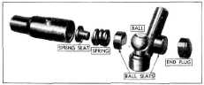
FRONT AXLE TIE ROD
The front
axle tie rod is of the ball, seat and spring type, similar to the steering
connecting rod construction.
Refer to
Fig. 43, and note how parts are assembled. The parts on both ends are
assembled in the same manner.
First the spring seat, then the spring and ball seat, then the ball and
ball seat, and then the plug.
Ball seats should be assembled so that notches line up with ball
neck.
To properly
adjust this front axle tie rod:
1. Remove cotter pins.
2. Screw plugs in tight until springs are
compressed solid and back
off to first cotter pin hole.
3. Insert and clinch cotter
pins.
4. Lubricate both ends of tie
rod.
To remove
the tic rod from the front axle, remove the cotter pin, end plug and ball seat.
Screw end plug back into the
end of the tie rod until the ball is in the center of the opening. A
light tap with a soft hammer
will remove the tic rod from the ball. |
||
 |
|||
|
Fig. 43-Front Axle Tie Rod
1/2-TON PANEL TRUCK STABILIZER
A ride
stabilizer is used at the front of the 1/2-Ton Panel Truck to prevent excessive
sidesway on turns. The design is similar to that of the
passenger car models, the
major difference being in the changes necessary to adapt it to the
conventional front
axle. |
|||
|
|
|||