1942 - 1947 CHEVROLET SHOP MANUAL
Section 5 - Brakes
|
|
||||
|
5-1 |
||||
|
|
||||
|
Section
5
HYDRAULIC BRAKES |
||||
|
|
||||
|
The braking system of all 1942
passenger cars and trucks combines hydraulically operated service
brakes with mechanically operated emergency brakes. Fundamentally, the
braking system of the passenger cars and trucks is the same. However, due
to the variance in the brake lining sizes, wheel brake drum sizes, and
frame design there are several differences in the braking systems.
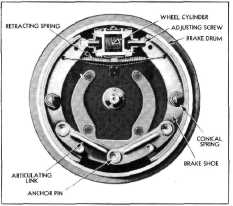
Fig. 1 shows the brake construction. |
the piston into the space between
the primary cup and the check valve, keeping sufficient fluid in the lines at all times. The holes in the valve
cage allow the fluid to flow through the cage and around the lip of
the rubber valve cup and out into the lines during the brake application.
When the brake is released the lip of the rubber valve cup seals the holes
in the valve cage and the valve is forced off its seat, permitting the
fluid to return to the main cylinder. The push rod assembly is held in the
opposite end of the housing by means of a snap ring. The rubber boot that
fits around the push rod and over the end of the housing prevents dirt or
any other foreign matter from entering the main cylinder. Fig.
2. |
|||
 |
||||
 |
||||
|
Fig- 1—Front Brake Mechanism
In order to thoroughly understand
the operation of the hydraulic brake system, it is necessary to have a
good knowledge of the various parts and their functions and to know what
takes place throughout the system during the application and release of
the brakes.
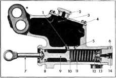
MAIN CYLINDER
The piston in the main cylinder,
Fig. 2, receives mechanical pressure from the push rod and exerts pressure
on the fluid in the lines, building up the hydraulic pressure which moves
the wheel cylinder pistons. The primary cup is held against the piston by
the piston return spring which also retains the return valve against its
seat. The spring maintains a slight pressure in the lines and in the wheel
cylinders to prevent the possible entrance of air into the system. The
secondary cup, which is secured to the opposite end of the piston,
prevents the leakage of fluid into the rubber boot. The holes in the
piston head are for the purpose of allowing the fluid to flow from the
annular space around |
||||
|
Fig. 2—Main Cylinder Cross
Section |
||||
|
1 Inlet
2 Filler
Plug
3
Reservoir
4 Housing
Cover
5 Compensating
Port
6 End
Plug
7 Push Rod |
8 Piston
Cup—Secondary
9 Piston
10 Piston Cup—Primary
11 Spring
12 Valve
13 Valve Seat
14 Outlet |
|||
|
WHEEL CYLINDER
The wheel cylinder, Fig. 1, is a
double piston cylinder, the purpose of the two pistons being to distribute
the pressure evenly to each of the two brake shoes. The rubber piston cups
maintain pressure on the pistons and prevent the leakage of fluid
past the pistons. The adjusting covers serve two purposes: first, to cover
the ends of the cylinder and prevent the entrance of dirt and foreign
matter into the cylinder, and second, serve as a means of adjusting the
brake shoes to the proper drum clearance, being threaded to receive the
slotted adjusting screws which fit the webs of the brake
shoes. |
||||
|
|
||||