1942 - 1947 CHEVROLET SHOP MANUAL
Section 5 - Brakes
|
|
|||
|
5-2 |
|||
|
|
|||
|
SEQUENCE OF EVENTS
DURING
APPLICATION AND
RELEASE
OF
BRAKES
As
pressure is applied to the brake pedal and is transmitted from the push rod to the
piston in the main cylinder,
the primary cup closes the compensating port and fluid is forced
through the holes in the valve
cage, around the lip of the rubber valve cup, into the pipe lines and into the
wheel cylinders. This pressure
forces the pistons in the wheel
cylinders outward, expanding the brake shoes against the drums. As the pedal is
farther depressed, higher
pressure is built up within the hydraulic system, causing the brake shoes to
exert greater force against
the brake drums, Fig. 1.
As the
pedal is released, the hydraulic pressure is relieved and the brake shoe
retracting springs draw the shoes
together, pressing the wheel cylinder pistons inward and forcing the fluid
out of the wheel cylinders back
into the lines toward the main
cylinder. The piston return spring in the main cylinder returns the piston to the
pedal stop faster than the
brake fluid is forced back into the lines, creating a partial vacuum in that
part of the cylinder ahead of
the piston. This vacuum causes a small amount of fluid to flow
through the holes in the piston head,
past the lip of the primary cup and into the forward part of the cylinder.
This action keeps the cylinder filled with fluid at all times, ready for the next brake application.
As fluid is drawn from the
space behind the piston head it is replenished from the reservoir through
the inlet or breather port.
When the piston is in a fully
released position, the primary cup clears the compensating port, allowing excess fluid to
flow from the cylinder into the
reservoir as the brake shoe
retracting springs force the fluid out of the wheel cylinders.
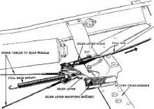
EMERGENCY BRAKE
The passenger car emergency brake
lever is located under the dash
on the left of the steering column and is connected to the idler lever
with rod-type linkage. The
idler lever is mounted in two
brackets riveted to the center of the second frame cross member. Two one-piece cables are
pivoted at the center of the
idler lever and are attached
to the rear brakes.
The pull
rod from the control lever is yoked at one end of the idler lever and provides
proper torque for emergency brake application, Fig.
3.
SERVICE OPERATIONS
To
properly maintain the braking system, servicemen must appreciate that a thorough
knowl- |
edge of the
system, absolute cleanliness, and careful workmanship are very
important. Absolute cleanliness is
necessary because any foreign matter in the system will tend to
clog the lines, ruin the rubber cups
of the wheel and main cylinders, and cause inefficient operation or even failure
of the |
||
 |
|||
|
Fig. 3—Emergency Brake Linkage |
|||
|
braking
system; dirt or grease on a brake lining will cause that lining to take effect first
on brake application and fade
out on heavy brake application. Careful workmanship will result in a
well done
job.
BLEEDING THE HYDRAULIC BRAKE SYSTEM
The
hydraulic brake system must be bled whenever a pipe line has been disconnected,
when a leak has allowed air to
enter the system or at any time the system has been opened. A leak
in the system may sometimes be
evident through the presence of a "spongy" brake pedal. Air trapped in the
system is compressible, and
does not permit all pressure applied to the brake pedal to be
transmitted through to the
brake shoes. The system must be absolutely free from air at
all times.
The longest
pipe line of the brake system should be bled first. The proper sequence
for bleeding is: left rear, left
front, right rear, and lastly, right front. During bleeding operations the main
cylinder must be kept at
least half full of hydraulic brake fluid. The main cylinder filler,
J-713-C, Fig. 4. automatically
maintains the correct fluid level in the main cylinder during
bleeding.
TO BLEED THE HYDRAULIC BRAKE SYSTEM
Carefully
clean all dirt from around the main cylinder filler plug.
Remove
filler plug, install adapter and automatic filler. Open automatic valve in the
filler.
Remove
bleeder valve screw. Attach bleeder drain, Fig. 5, keeping the end of the drain
hose below the surface of the fluid in the
jar. |
|||
|
|
|||