1942 - 1947 CHEVROLET SHOP MANUAL
Section 6 - Engine
|
|
|||
|
6-16 |
|||
|
|
|||
|
This can
be done with the dial indicator as shown in Fig. 30. The face and rim of the
flywheel should not
exceed .008" run-out.
CONNECTING RODS
Chevrolet
connecting rods are made of special steel, drop forged and of unusual strength.
The connecting rod bearings are of the "spun-in" type. By this is meant
that the babbitt lining or bearing part is an integral part of the rod
assembly. The metal is not
simply poured or die cast into place. Instead, the rod and cap forgings are
clamped to a special face plate
which revolves at a high rate of speed. The centrifugal action set up
causes the molten metal to be
forced out towards the walls of
the rod, and, in cooling becomes practically a part of the connecting
rod.
The connecting rods are then
checked for alignment, weighed and go through a series of other important dimension checks. The rods that
pass this very careful inspection are then placed in new engines or
sent out for service.
Every time a connecting rod is
removed and is |
to be
replaced in an engine, or a new connecting rod is to be installed, it should be
carefully checked for alignment
on a connecting rod alignment fixture.
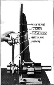
Connecting Rod Alignment
The
connecting rod alignment fixture, Fig. 31. is used to accurately check the alignment of
the piston and pin with the connecting rod bearing.
The
connecting rod is clamped on the arbor, as shown in the illustration, and by use of
the "V" block resting against
either the piston or the piston pin, the amount of misalignment will be
shown between the pins on the
"V" block and the face plate
on the fixture.
To check
the rod on this fixture, place the pin in the rod and assemble the rod and pin to
the arbor on the fixture. Place
the "V" block on the piston
pin, and move the rod and arbor toward the face plate. The vertical pins will
indicate a cocked or bent rod.
By that it is meant that if the two top pins rest against the face plate and
the two bottom pins are away
from the face plate, the rod is
cocked or bent. The same is true if the two bottom pins rest against the face plate and
the two top pins are away from
it.
If the two horizontal pins, on the
front side, rest against the face
plate and the two hack pins are away from it, the rod is twisted. The same
is true if the two back pins
rest against the face plate and the two front pins are away from the face
plate.
The fixture is sufficiently strong
to hold the connecting rod, if
straightening is necessary, which can be done with a bending
bar.
After this
check has been made and the rod straightened, if necessary, so that all
four pins touch the face
plate, the "V" block should be placed on the piston pin so that the "V"
block rests against the
outside edge of the connecting rod and then the rod and "V" block is moved toward
the face plate until all four
pins touch. The index, on the
bottom of the fixture, is then placed so that it touches the large end of the connecting rod
bearing. Remove the rod
from the arbor and turn it around. Assemble it again to the arbor and
place the "V" block on the piston pin in the same place as when checking the other side. Move rod
and "V" block toward the face
plate until either the index
touches the bearing or the pins touch the face plate. If the index does not touch the
rod bearing with the four pins touching the face plate, the distance between the rod bearing and the
index should be checked with a feeler gauge. If this distance is more than .025" the rod should be
straightened until both the
pins touch the face plate and
the index touches the rod bearing, within .025". |
||
 |
|||
|
Fig. 31—Connecting Rod Alignment
Fixture |
|||
|
|
|||