1942 - 1947 CHEVROLET SHOP MANUAL
Section 6 - Engine
|
|
||||
|
6-17 |
||||
|
|
||||
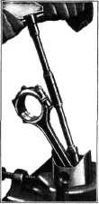 |
If the
index touches the rod bearing and the
four pins do not touch the
face plate, the distance
between the pins and the face
plate should also be checked
with a feeler gauge. If this
distance is more than
.025" the rod should be
straightened until the
pins, on the "V" block,
touch the face plate and
the index touches the
rod bearing within.
025".
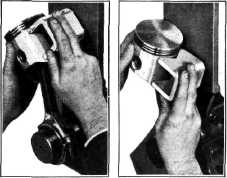
Assembling Connecting Rod
to Piston
Place the piston in a piston vise.
Fig. 32. Assemble the rod to the
|
make this
check, the connecting rod and piston assembly is mounted on the alignment
fixture and the piston is set in line
with the connecting rod. Then
place the "V" block on the piston skirt. If both pins on the block contact
the face plate the rod is not
cocked. Fig. 33. Then, with the "V" block on the piston skirt and the pins
against the face plate, tip the piston first in one direction and
then in the other, Fig. 34. If the
pins on the block |
||
 |
||||
|
Fig. 32—Assembling Connecting Rod
to Piston |
piston and
install the |
|||
|
pin. Before tightening clamp screw, center the piston pin in the
piston and the rod in the center of the two piston pin bosses. Tighten the clamp screw and move
piston on the pin from side to
side, checking to see that the
piston pin does not extend beyond the outside of the piston.
NOTE—The connecting rod should
never be clamped in a bench vise when installing the piston on it as
tightening the clomp screw will likely twist the rod.
Assemble
the piston and connecting rod
assembly to the
align |
||||
|
Fig. 34—Checking Piston and
Connecting Rod Assembly for Twisted Connecting Rod
remain
against the face plate, there is no twist in the connecting rod. But if one pin leaves
the face plate while the
piston is being tipped in one direction and the other pin
leaves the face plate while the piston
is being tipped in the other direction, the connecting rod is twisted and should be
straightened until both pins follow the face plate.
Assembling Piston and
Connecting Rod to Engine
In production, both the connecting
rod and the bearing cap are stamped on
the camshaft side with the number of the cylinder in which they are
to be assembled. When the rods are
being reassembled they should be replaced in the same cylinder from
which they were removed with the
stamped numbers on the camshaft side.
The
condition of the crank pins on the crankshaft should be checked when installing new
rods. Damaged crankpins can
only be corrected by the installation of a new crankshaft, as it is
impossible to insure connecting
rod bearing life on a damaged crankpin.
The gaps
in the three piston rings should not be in line, one above the other. Stagger
the gaps so that they will be equally spaced around the piston but
so that there is no ring gap directly over the piston pin end. Gaps in this
position will allow gases to
leak by at this point. |
||||
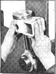 |
ment
fixture, Fig. 33, and check with the
"V" block resting against the
piston skirt to see that
the rod and piston are
in alignment. Both pins
on the "V" block should
rest against the face of
the plate on the fixture.
The piston should be in
the same alignment as
the connecting rod when
this check is
made.
A quick
check of a |
|||
|
Fig. 33—Checking Piston end
Connecting Rod Assembly |
piston and
connecting |
|||
|
rod
assembly for both |
||||
|
cock and
twist can be made without
disassembling the rod from the piston. This method saves considerable time
on any repair operation that
does not normally require
the removal of the rod from the piston. To |
||||
|
|
||||