1942 - 1947 CHEVROLET SHOP MANUAL
Section 6 - Engine
|
|
|||
|
6-18 |
|||
|
|
|||
|
The
connecting rod and piston should be assembled in the cylinder bore with
the piston pin clamp bolt on the
camshaft side of the engine.
Lubricate
either the piston or the cylinder bore and slip the pistons into the bores, using
extreme care. Do not force the rings into the bore. Compress the rings with the piston inserter,
J-975, and slip the assembly
into the bore until the chamfer on the inserter enters the chamfer at the
top of the cylinder bore, Fig.
9. With the inserter in this position, the piston rings will readily
enter the bore.
Lubricate
the crankpin and pull the connecting rod down onto it, making sure that
the numbered side of the rod is
toward the camshaft. Install three .002" shims on each connecting rod
bolt and then install the
bearing cap with the numbered side toward the camshaft. Install the
connecting rod oil dipper with
its open side toward the camshaft. Assemble and tighten the
nuts.
Adjusting Connecting Rod Bearings
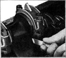
Remove
shims, an equal number from each side of the bearing, until the rod cannot
be snapped forward and backward on
the crank pin by hand, but can
be tapped back and forth with a light blow of an 8 ounce hammer. Then place one
.002" shim on one side, being careful to keep the number of shims on each side equal, if possible.
When the bearing is properly
fitted, it should be possible to snap the rod back and forth on the crank
pin with one hand, Fig,
35. |
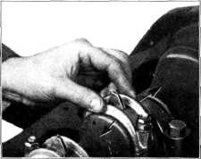
of the
crankpin with a feeler gauge. This clearance should not be less than .004" nor more
than .011", Fig.
36. |
||
 |
|||
|
Fig. 36—Checking Connecting Rod End Clearance
Lock the
connecting rod bolt nuts by installing new "pal" nuts. The "pal" nuts must be
installed with the open side of
the nut toward the end of the bolt. Turn the "pal" nut up finger tight and
then 1/2 turn
more.
As a final
and last check to be sure that the piston and rod assembly will travel true
with the bore, check the
clearance between the piston pin end of the connecting rod and the piston
pin bosses on the piston with
a feeler gauge This should not
be less than .025".
ENGINE OILING SYSTEM
Engine
lubrication is supplied by a positive driven gear pump equipped with a spring
loaded by-pass valve to control
the maximum pressure at high
speeds and when the engine oil is heavy and sluggish during cold weather
starting.
The engine oiling system provides
positive pressure lubrication to
the main bearings and camshaft bearings. The connecting rod
bearings are lubricated at low speeds
by means of dippers on the rod
bearing caps which dip into oil filled troughs in the oil pan. At high speeds
lubrication is amply maintained by oil nozzles. Cylinder walls
and pistons are lubricated by the oil
spray thrown off by the connecting rods. Lubrication of the valve
mechanism is accomplished by oil
being pumped to the hollow
rocker arm shafts.
MAIN AND CAMSHAFT BEARING
LUBRICATION
The oil flow is from the pan,
through the pump screen and oil pump
to the block fitting, and then |
|||
 |
|||
|
Fig. 35—Checking Connecting Rod Bearing
Fit
If it is not possible to keep the
number of shims equal on each side
for all bearings, it is preferable to have the greater number of shims on
the camshaft side.
Check
connecting rod end clearance between the upper half of the connecting rod and the
side |
|||
|
|
|||