1942 - 1947 CHEVROLET SHOP MANUAL
Section 6 - Engine
|
|
|||
|
6-56 |
|||
|
|
|||
|
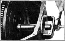
Fig. 115,
turn the large nut against the clamp, pulling out the
retainer. |
Clutch Reassembly
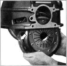
1. Install the pressure plate in the cover
assembly, making sure to line
up the two "O" marks: one on
the driving lug of the pressure plate and the other on the flange of the cover, Fig.
112. This must be done to
insure proper clutch balance.
2. Install the three pressure plate retracting
springs, Fig. 112. The clutch is now ready to
reassemble to the
engine.
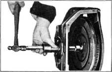
3. Hand-crank the engine until the "X" mark on
the flywheel is at the bottom.
Install the clutch disc, pressure plate, and cover assembly and
support them with the clutch
pilot tool. Turn the clutch
assembly until the "X" mark on the clutch cover lines up with the "X" mark on
the flywheel, Fig. 117. Then
install the attaching |
||
 |
|||
|
Fig. 115—Clutch Pilot Bearing Retainer
Remover
The roller
bearing may now be removed with the fingers.
Before installing the bearing, it
should be packed with a very small amount of special high temperature
grease.
The
bearing may then be installed in place at the end of the
crankshaft.
The
special driver shown in Fig. 116 should be used when installing a new
retainer. |
|||
 |
|||
 |
|||
|
Fig. 117-lnstalling Clutch Assembly
bolts,
tightening each one a turn at a time to prevent distorting the cover as the spring
pressure is being taken up. Remove the clutch pilot tool.
4. Pack
the ball seat in the fork with a small amount of high-melting point grease.
Install a new spring retainer
in the groove of the clutch fork if the old retainer is worn or
damaged. Reassemble the
fork in position in the clutch housing and snap the fork onto the
ball.
CAUTION—Make certain the
retainer is installed with
the high side of the retainer UP, away from the bottom of
the ball bearing, and the open end of retainer on the
horizontal. |
|||
|
Fig. 116—Clutch Pilot Bearing
Retainer Inserter
This driver is constructed with a
centering collar which fits in the
pilot hole and has a pilot on its end centering in the
bearing.
In
operation a retainer is placed on the end of the driver with the flat side
toward the bearing. The tool is
placed into position with the centering collar in the transmission pilot hole in the
flywheel housing. The handle
is then moved forward until the
retainer begins to enter the hole in the flywheel. Tap the end of the driver lightly with a
hammer until the retainer is
seated. |
|||
|
|
|||