1942 - 1947 CHEVROLET SHOP MANUAL
Section 7 - Transmission
|
|
||||
|
7-12
case and installing the countershaft, Fig.
20. |
NOTE—Under ordinary
circumstances it is not necessary to remove the shifter assembly from the
cover.
Remove the four capscrews from the
transmission cover and remove the cover and gasket. It will be
noticed that the two front screws are special screws having extended ends
that also lock the shifter shafts in the transmission case.
Lift out the shifter interlock.
Drive the shifter shafts from the
case with a soft steel drift, driving them from the rear of the case to
the front. Both of these shafts are .003" larger in diameter where they
fit into the front of the case. Both front and rear diameters are ground to close limits so that the
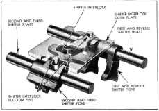
shafts will fit snugly in the case. Fig. 21 shows the parts of the
shifter mechanism. |
|||
 |
4.
5. |
|||
|
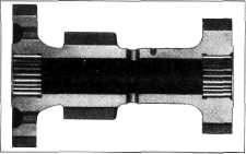
Fig. 20—Roller Bearing Countergear
2. Install the countergear in the case;
lubricate the forward
thrustwasher and install it between the countergear and
case.
3. Feed the assembly tool. T-1617 (inset in
Fig. 12) in from the front,
tapered end first, picking up
the forward thrustwasher and the countergear, being careful to keep the roller
bearings in
place.
4. Lubricate the countershaft and install it
from the front, pushing the assembly tool ahead of it, Fig. 12.
5. Lubricate the rear thrustwasher and slip it
between the countergear and
case, picking it up with the
assembly tool as it is pushed through by the shaft.
The fiat on the forward end of the
shaft engages the clutch housing when the transmission is installed in the
chassis, and keeps the countershaft from turning. This flat must be
horizontal and at the top or the transmission cannot be assembled to the
clutch housing.
NOTE—The step at the end of the
countershaft should be flush with the front face of the case, or
approximately 1 64" below the face, to maintain proper transmission
alignment.
DISASSEMBLY OF THE SHIFTER MECHANISM
1. Remove the four capscrews from the gearshift
lever
housing.
CAUTION—These screws should be
backed off evenly, or two of the screws should be removed and replaced
with longer ones, in order to relieve the tension of the gearshift lever
spring before removing the retainer.
2. Remove the retainer, lever, ball seat, spring
and gasket. |
||||
 |
||||
|
Fig. 21-Shifter Mechanism
6. The transmission can now be
overhauled in the same manner as the passenger car
transmission.
REASSEMBLY OF SHIFTER MECHANISM
1. Install the shifter yoke lock balls and
springs in the side of the
transmission case.
2. Install the shifter yokes in the sides of
the case, placing the first
and reverse yoke over the first and reverse sliding gear, and the second
and high yoke over the ring on
the clutch sleeve.
3. Install the shifter shafts from the front
of the case, the longer of the
two being the first and reverse shaft. Line up the lock holes in the
shafts with the two front cover
capscrew holes in the top of
the case.
4. Lay the shifter interlock in slots in the
shifter yokes, with the pins
upward. The interlock shifter
lies in the slots so that the hole is closer to the second and high speed shifter
shaft. |
||||
|
|
||||