1942 - 1947 CHEVROLET SHOP MANUAL
Section 7 - Transmission
|
|
|||
|
7-13 |
|||
|
|
|||
|
5. Assemble the transmission cover and
gasket to the case, using the
two special capscrews at the front.
6. Place the gearshift lever housing over the
shift lever; install the shift
lever spring and ball seat in the retainer.
7. Assemble the retainer and gasket to the
transmission cover with
the four capscrews, drawing the screws down evenly to prevent the shift
lever spring from exerting a
strain on the die-cast
retainer, or by using two longer capscrews in opposite holes to aid in compressing the
spring enough to start the
short screws in place; then
remove the two long screws and replace them with the other two regular
screws.
8. Check the operation of the transmission by
shifting into all
gears.
VACUUM GEARSHIFT
(Passenger Cars)
The Vacuum
Gearshift operates essentially the same as on previous models. In this system
both physical and vacuum effort
are combined to effect transmission gear changes. The majority of
the effort, however, is exerted automatically by the engine vacuum when the engine is running.
The transmission gears may be
shifted manually without
the aid of the vacuum effort, which is also the case when the engine is not
running.
VACUUM CYLINDER
When the
gearshift lever is in neutral position it will be noted that the valve is in a
position that admits atmospheric pressure to both sides of
the |
piston.
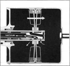
When the gearshift lever is moved forward as when shifting into either reverse or
second speeds, the inner
sleeve valve is moved forward and vacuum from the engine is applied
to the forward side of the piston, and
outside air passes to the rear
side, Fig. 22. This causes the piston to move forward in the cylinder.
When the gearshift lever is moved
backward, as when shifting into
either low or high speeds, the inner sleeve valve is moved backward
in the piston rod. This uncovers the
rear port in the piston rod and applies the engine vacuum to the rear
of the piston at the same time the forward port is opened to the outside air and the piston is moved
backward, Fig.
23. |
||
 |
|||
|
|
|||
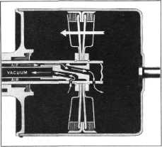 |
Fig. 23—Vacuum Cylinder in
Position when Shifting into Low or High Speeds |
||
|
GEARSHIFTING
In the following explanation of
the action of the shifting mechanism
when a change of gears is desired, we will assume a definite gear
change for an example. When a shift is to be made from neutral
into second gear, the initial forward movement of the gearshift lever causes the gearshift
control rod to move forward
and, in so doing, pulls the vacuum cylinder valve rod forward,
admitting vacuum to the forward
side of the piston and outside air to the rear as shown in Fig.
22.
This is
accomplished without moving the transmission operating lever because the control
rod clevis pin is a loose fit
in the transmission operating lever, the gearshift control rod
links, and the sleeve valve
link which is a loose fit on the vacuum cylinder piston rod yoke
pin. |
|||
|
Fig. 22—Vacuum Cylinder in
Position when Shifting into Reverse or Second Speeds |
|||
|
|
|||