1942 - 1947 CHEVROLET SHOP MANUAL
Section 7 - Transmission
|
|
||||
|
7-14 |
||||
|
|
||||
|
As soon as
the piston starts to move forward, the piston rod yoke pin carries the
upper end of the reactionary levers
forward. This action results in
the upper end of the idler levers, which are pivoted on the pin, being moved
backward.
This action
would tend to move the vacuum valve
backward, closing the port and cutting off the vacuum, if the movement of the gearshift
lever on the steering column
was stopped.
Therefore,
it is necessary to keep moving the gearshift lever until the shift is
completed, so that the force
exerted by the vacuum cylinder may move the shifter operating lever forward
and shift the gears in the
transmission. When the shift is completed, the action described
above closes the vacuum
valve.
The
foregoing description applies to the action which takes place during the shift into any
gear. The only difference is
that the lever system moves in
the opposite direction while shifting into low or high speeds.
GEARSHIFT LEVER Disassembly
To remove
the gearshift lever without disturbing the balance of the assembly, shift into
reverse gear position, depress
the pivot pins approximately 3/32" then lift up on the lever and pull
it outward.
The
gearshift lever anti-rattle spring and pivot pin spring may be removed by removing the
pivot pins, compressing the
legs of the spring and lifting it upward.
Reassembly
Before
reassembling the gearshift lever, the ball on the control shaft should be
lightly coated with graphite
grease.
Install the
anti-rattle |
STEERING COLUMN ASSEMBLY
Disassembly
1. Disconnect the gearshift control rod from
the shift lever by removing the
cotter pin and flat washer
from the swivel.
2. Disconnect the selector rod from the
selector lever by removing the
cotter pin and flat washer.
3. Remove the clamp bolt from the gearshift
control shaft lever and remove
the lever and spring,
4. Remove the horn button or ornamental cap
and steering wheel nut. Using
steering wheel puller J-I618,
remove the steering wheel. (For a description of this puller and its
use, refer to "Steering Gear
Assembly," Section 9, "Steering
Gear Removal" Division.)
5. Remove the nuts and lockwashers from the
instrument panel to mast
jacket clamp and remove the
clamp.
6. Remove the two clutch head screws which
attach the gearshift control
upper support to the mast jacket. The control shaft and upper support may now be pulled up out of the
lower
support.
7. To remove the gearshift lever, compress the
pivot pins, lift up on the
lever and pull it outward. Then remove the pivot pins and
anti-rattle and pivot pin
springs.
8. Remove the control shaft by pulling it out
of the upper support.
9. The gearshift lever swivel may be removed by
unscrewing it from the upper
support.
10. The
gearshift control lower support assembly may be removed from the steering
mast jacket by removing the nuts from the lower support clamp. |
|||
|
|
||||
|
springs in ball and over neck of control shaft and pivot pin spring in swivel, and thread
the pivot pins onto the ends of the spring and into the holes in
the gearshift lever swivel. Thread the gearshift lever over this assembly,
compress the pivot pins, and, at the
same time, press down
|
 |
 |
||
|
on the top of the
lever |
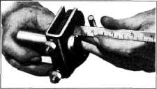
Fig. 25—Positioning Lower Support Bushing
If the
bushing in the lower support is worn, it should be pressed out of the lower support
and a |
|||
|
until the
pivot pins snap |
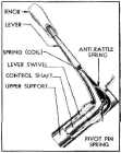
Fig. 24—Vacuum Gearshift Lever
Assembly |
|||
|
into
place. Fig. 2 4 shows the gearshift
lever assembly in cross-section |
||||
|
|
||||