1942 - 1947 CHEVROLET SHOP MANUAL
Section 7 - Transmission
|
|
|||
|
7-16 |
|||
|
|
|||
|
2. Install the steering wheel and adjust the
horn button or horn blowing
ring for contact.
3. Move the lower support bracket up or down
on the mast jacket until the
distance between the under side
of the bracket and the upper side of the shift control lever is 3/4",
Fig. 28. Tighten the lower
support clamp bolts.
NOTE—Care should be taken not to
over tighten these nuts or there is
danger of crushing the mast jacket.
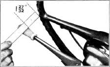
4. Loosen the check nut on the selector rod
adjustment. Pull the
selector rod forward as far as
possible, then adjust the swivel by screwing it up or down on the rod until the distance
between the under side of the
steering wheel and the top
side of the gearshift lever is 1-27/32" when the rod is connected to the
selector |
Disassembly
1. Remove the shift control rod from the
reactionary
lever,
2. Remove the vacuum hose from the vacuum
inlet stack. Then slip the
forward end of the rubber boot
off the rear end of the metal boot.
3. Remove the two screws which fasten the two
halves of the metal boot
together, then lift off the
outer half.
4. Remove the piston rod yoke clevis pin. Push
the piston rod into the
cylinder to disconnect it from
the reactionary levers. Then reinstall the clevis pin through the piston rod yoke
and valve link to prevent
upsetting the valve adjustment.
5. Loosen the operating lever clarnp bolt and
pull the reactionary lever
system off the transmission operating lever shaft. The other half
of the metal boot may then be
removed.
6. Wash the reactionary levers in clean
gasoline or cleaning solvent to remove all old grease and dirt. Examine the rubber seal at the front
of the metal boot; if damaged
it should be replaced.
Reassembly
1. Coat the reactionary levers lightly with
graphite grease, working
it between levers and onto
pins. Place the inner half of the metal boot over the transmission operating lever
shaft. Thread the rubber seal over the idler lever and install the reactionary lever
system on the operating lever
shaft, just beyond chamfered
end of shaft, and tighten the clamp bolt.
2. Pull the piston rod forward and connect its
yoke and the valve link to the
reactionary levers. Then
install the piston rod valve clevis
pin.
3. Assemble the outer half of the metal boot
to the inner half and install
and tighten the two screws.
4. Slip the forward end of the rubber boot
over the rear end of the metal
boot. Install the vacuum hose
and shift control rod. |
||
 |
|||
|
Fig. 29—Adjusting Vacuum Gearshift Lever |
|||
|
trol lever,
Fig. 29. Install the flat washer and cotter pin on the swivel pivot and lock the
selector rod adjustment with
the check nut.
5. To
adjust the shift control rod, set the gearshift lever in the horizontal position.
Loosen the check nut on the
control rod. Push the shift control rod back until all clearance is
taken up (noting the location
of swivel with reference to
shift control lever), then pull it forward until all clearance is taken up, noting
location of swivel. Midway
between these two points is neutral valve position. While in this
position, adjust the swivel on
the control rod by screwing it up or down on the rod until the
pivot just enters the shift
control lever. Install the flat
washer and cotter pin on the swivel pivot and lock the shift control rod
adjustment with the check nut.
REACTIONARY LEVERS
The reactionary levers are a
riveted assembly; therefore, the only service operations are removal,
cleaning, lubricating, and
replacement. |
|||
|
VACUUM CYLINDER |
|||
|
Removal |
|||
|
1. Remove the vacuum and air hoses, outer half
of reactionary lever metal
boot, and disconnect the
piston rod yoke and valve links from the reactionary levers, as explained under
the heading "Reactionary
Levers."
2. Remove the cotter pin and nut from the
cylinder mounting stud
and remove the cylinder from
the bracket. |
|||
|
|
|||