1942 - 1947 CHEVROLET SHOP MANUAL
Section 7 - Transmission
|
|
|||
|
7-17 |
|||
|
|
|||
|
Replacement
1. Assemble a rubber cushion and steel retainer
on the cylinder mounting stud;
insert the stud through the
hole in the bracket and install a steel retainer, rubber cushion, flat washer,
and castle nut on the mounting
stud in the order named.
Tighten the nut just enough to permit inserting the cotter pin and no more. It is
essential that flexibility
be maintained at this point.
2. Connect the valve link and piston rod yoke
according to instructions
given under the heading "Reactionary Levers."
3. Install the vacuum and air hoses and
tighten the hose
clamps.
Lubrication
When it
becomes necessary to lubricate the vacuum cylinder it must be removed because
of its mounting
angle.
With the
cylinder set up on its mounting end, pull the valve link forward to open the
vacuum port on the forward side
of the piston, and, while holding the link, introduce 1/2 ounce of
shock insulating fluid
into the cylinder through the vacuum inlet stack. Allow sufficient time for the
fluid to flow down into the
cylinder. Push the valve rod all the way into the piston rod, and
introduce 1/2 ounce of shock insulating fluid through the
vacuum inlet stack. Again allow sufficient time for the fluid to flow down into the
cylinder.
Move the
piston rod in and out of the cylinder several times, at the same time turning the
cylinder to spread the
fluid over the cylinder walls and piston leather. Then reassemble the
cylinder to its bracket, and connect the piston rod yoke and valve link to
the reactionary lever system.
Washing
To wash the
cylinder internally without disassembling, follow the instructions under
"Lubrication" with the following exceptions:
Two ounces of shock insulating
fluid should be injected into the cylinder through the vacuum inlet
stack.
After the
piston rod has been moved back and forth several times, hold the piston in the
down position and move the valve to allow the fluid to drain out
through the valve ports.
Repeat the process, after which
the fluid remaining in the
cylinder after draining should be of sufficient quantity and cleanliness to
lubricate the cylinder.
AIR CLEANER
Every 10,000 miles the air cleaner
should be removed and cleaned as
follows: Disconnect the air hose from the vacuum cylinder. Remove
the |
two bolts
which attach the air cleaner to the frame side rail. Wash it in clean gasoline or
cleaning solvent. Allow
the gasoline to drain off and dip it in engine oil. Allow the excess oil to drain
off and reinstall the air
cleaner to the frame side rail, making sure the soft rubber gasket is in
place.
VACUUM CYLINDER VALVE ADJUSTMENT
Should it
become necessary to adjust the valve in the vacuum cylinder the procedure
outlined below must be
followed very closely:
1. Slip the forward end of the rubber boot off
the rear end of the
reactionary lever metal boot.
2. Remove the two screws which fasten the two
halves of the metal boot
together, and remove the outer
half, exposing the reactionary levers.
3. Remove the piston rod yoke clevis pin. Push
the piston rod into the
cylinder far enough to disconnect the yoke and valve from the
reactionary levers.
Install the special adjusting bushing J1452-5, and replace the clevis
pin.
4. With the engine running, to provide vacuum,
move the valve link away from
the cylinder until all clearance between the special
adjusting bushing and the
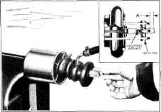
valve link is toward the front of the car as shown at "A1' in
Fig. 30. |
||
 |
|||
|
Fig. 30—Valve Links Away From the Cylinder
In this position the piston rod
should move slowly
outward.
Now move
the valve link toward the cylinder until all clearance between the adjusting
bushing and the valve
link is toward the rear of the car as shown at "B" in Fig. 31. In this
position the piston rod should
move slowly inward. Should the piston move outward but will not
move inward, the valve link is
adjusted too far towards the
cylinder on the valve rod. To correct this condition, remove the clevis
pin and unscrew the valve link
on the valve rod 1/2
turn at a time until proper valve action is obtained. On the other hand, if the
piston |
|||
|
|
|||