1942 - 1947 CHEVROLET SHOP MANUAL
Section 7 - Transmission
|
|
|||||
|
7-18 |
|||||
|
|
|||||
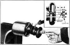 |
pin and screw the valve link onto
the valve rod 1/2 turn at a time until proper valve action is
obtained.
5. Reassemble the piston rod yoke
and valve to the reactionary levers according to instructions given under
the heading "Reactionary Levers." |
||||
|
VACUUM CYLINDER VALVE FRICTION SPRING
To install
this spring remove the outer half of the reactionary lever metal boot.
Disconnect reactionary levers from vacuum cylinder. Pull out
the valve rod in the vacuum cylinder
and snap the friction spring in
place about midway between the
valve and the valve rod guide.
NOTE—The closed end of the
spring should be toward the
back of the cylinder. |
|||||
|
Fig, 31-Valve Links Toward The Cylinder
moves
inward but will not move outward, the valve link is screwed too far out on the
valve rod. To correct this
condition remove the clevis |
|||||
|
|
|||||
 |
|||||
|
|
|||||
|
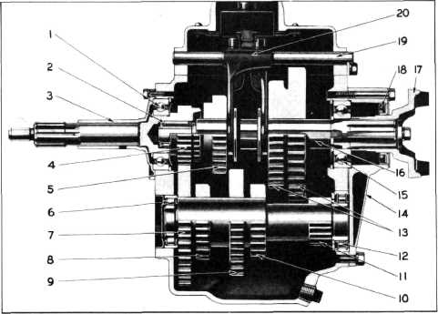
Fig. 32—Truck Four-Speed Transmission {3/4 Ton Long Wheelbase
Panel and All I-1/2 Ton Trucks) |
|||||
|
|
|||||
|
1
Clutch Gear Bearing
2
Main Shaft Pilot
Bearing
3
Clutch Gear Bearing Retainer
4
Clutch Gear
5
High Speed Sliding Gear
6
Countershaft Front Bearing
7
Countershaft Drive Gear |
8
Reverse Countergear
9
Third Speed Countergear
10 Second Speed Countergear
11 Low Speed Countergear
12 Countershaft Rear
Bearing
13 Low, Second and Reverse Speed Sliding
Gear |
14 Rear Bearing Retainer
15 Main Shaft Rear Bearing
16 Main Shaft
17 Universal Joint Yoke
18 Oil Seal
19 Gear Shifter Shaft
20 Shifter Forks |
|||
|
|
|||||