1942 - 1947 CHEVROLET SHOP MANUAL
Section 7 - Transmission
|
|
|||
|
7-22 |
|||
|
|
|||
|
The
1/4" wide spacer goes between the second and third-speed gears. The 7/8" wide
spacer is assembled between the
third-speed and reverse gears,
and the 5/32" wide spacer between the reverse and counter drive
gears.
When
pressing the gears on the countershaft, the round keys should be used to keep the
keyways lined up. After the
gears are pressed into place, the round keys should be driven down 1/32" below
flush with the gear. Any burrs set up should be filed down smooth.
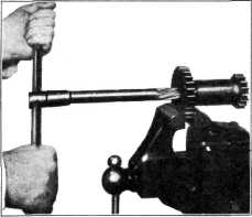
If the
bushings in the idler gear show signs of wear, they should be removed from this gear,
with the special tool, J-1662.
This same tool may be used to replace these bushings in the gear. After
the new bushings have been
installed, they should be
reamed to size, using KMO-349 reamer, Fig. 37, leaving a minimum clearance
of .002" between the bushings and shaft for proper
lubrication. |
REASSEMBLING THE TRANSMISSION
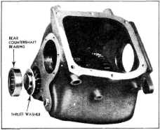
1. Assemble the countergear front bearing and
retainer to the case. The open side of the retainer should be toward
the outside and its edge flush with the case. Place the countergear and
shaft assembly in the transmission and assemble the thrustwasher and rear bearing as shown in
Fig. 38.
2. For the purpose of checking the end-play
between the countergear
and the case without further
assembly of the transmission, assemble the rear bearing retainer and
gasket to the rear face of the
case. Check the end-play between the rear thrustwasher and the shoulder on
the countergear. This end-play
should be from .015" to .045".
If it exceeds .045" shim between the front countershaft bearing and its
retainer until the end-play is
within the above limits.
3. Place the idler gear in the transmission
case and drive the idler gear
shaft into position from the
rear to the front, being careful to have the flat machined surface on the end of the
shaft in a vertical position,
and toward the countershaft.
4. Assemble the clutch gear and bearing and
bearing retainer to the
case, using a new gasket. Install the lock plates and capscrews, then
bend up the edges of the lock
plates against the hex. heads
of the capscrews. Dip the main shaft pilot bearing in transmission lubricant and
assemble it inside the clutch
gear.
5. Place the sliding gears in the
transmission, with the shifter
fork grooves toward each other, and assemble the main shaft and rear bearing
through these gears and into
the case.
6. Assemble the rear bearing retainer and
gasket to the case and tighten
the capscrews securely. Place the transmission in two gears to lock the
shafts and assemble the
universal joint to the end of
the mainshaft, using a shakeproof lockwasher, a flat washer, and a plain
lockwasher under the head of
the cap screw.
7. Assemble the speedometer driven gear and
shaft.
8. Assemble the universal joint ball and
collar to the rear bearing
retainer.
Transmission Cover Assembly
1. To disassemble the transmission cover,
remove the two screws which
attach the shifter shaft lock
plate and remove the plate.
2. When removing the three shifter shafts from
the cover, turn the shafts
one-half turn to raise the shift lock balls out of the notches in the
shafts, then push the shafts
out of the cover and shifter forks, being careful not to lose the lock
balls |
||
 |
|||
|
Fig. 37—Reaming Idler Gear Bushings |
|||
 |
|||
|
Fig. 38-Countershaft, Rear Bearing and Thrust
Washer |
|||
|
|
|||