1942 - 1947 CHEVROLET SHOP MANUAL
Section 7 - Transmission
|
|
|||
|
7-23 |
|||
|
|
|||
|
and
springs which are located in the shifter forks.
Should it become necessary to
replace the shifter interlock plate,
cut the heads from the four rivets and remove the plate. A new
plate may be installed by riveting it to the cover. |
gearshift
lever, using K-353 gearshift lever remover and replacer.
Install the transmission in the
truck. |
||
|
3/4-TON LONG WHEELBASE PANEL,
1-1/2-TON AND C.O.E. TRUCKS
The
foregoing instructions apply to the overhaul of all four-speed transmissions with the
exception of removing and
replacing the front universal joint front yoke, and the oil seal at the back
end of the rear bearing
retainer on trucks, using the Hotchkiss drive design at the transmission. The
trucks using this construction
at the back end of the transmission, Figures 32 and 35, are the
3/4-ton long Wheelbase panel,
all l-1/2-ton and Cab-Over-Engine models.
The
following overhaul instructions apply to the back end of Hotchkiss drive
transmissions:
After
disconnecting the universal joint, remove the capscrew and washer holding the
universal joint front yoke to
the back end of the main shaft. Remove the seven capscrews holding the
rear bearing retainer to
the case. Remove the bearing retainer with the yoke and oil seal. To
remove the front yoke of the
universal joint, the spring loaded oil seal must be removed from the
bearing retainer by pressure
applied to the front surface inside the bearing retainer. To remove
the oil seal from the front yoke of
the universal joint, the speedometer drive gear must first be pressed off
the hub of the yoke in an arbor
press, then the oil seal may be slipped off.
Installation of the oil seal, and
reassembly of the transmission is the reverse of the foregoing. Before
reassembling the oil seal, or
installing a new one, the seal must be thoroughly soaked in engine oil.
The speedometer drive gear
should be installed on the hub
of the universal joint front yoke, with the chamfered edge of the gear toward the
front end of the yoke. When
pressing the oil seal into the bearing retainer, care should be
used to line up the bolt holes in the
seal bolting flange with the holes in the back of the bearing
retainer. |
|||
 |
|||
|
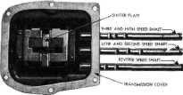
Fig. 39—Transmission Cover and Shifter
Shafts
Reassembly
1. In reassembling the transmission cover,
care must be used in installing
the shifter shafts. They should
be installed in the order shown in Fig. 39, namely, reverse speed, low speed
and high
speed.
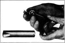
2. In assembling the shifter forks to the
shafts, first place the shift lock spring and ball in the fork. With the
special tool shown in Fig. 40, force the ball down on the spring in the
fork, then turn the tool
one-half turn to hold the ball
in position. This tool holds the shift lock ball and prevents it from jumping out while
the shaft is being installed. |
|||
 |
|||
|
CAB-OVER-ENGINE TRUCK
The
transmission of this model is of the same design as used on the conventional 1-1/2-ton
truck models. The service
operations on these units for removal and replacement are identical with
those on the conventional
1-1/2-ton truck with the exception of the removal of the remote
control gearshift. |
|||
|
Fig. 40-Method of Assembling Shifter Shafts Into
Forks
3. Install
the shifter shaft lock plate. Install the cover assembly and gasket to the
transmission case, making sure
that the shifter forks enter the shifter fork grooves in the gears.
Install the |
|||
|
|
|||