1942 - 1947 CHEVROLET SHOP MANUAL
Section 9 - Steering Gear Assembly
|
|
|||
|
9-6 |
|||
|
|
|||
|
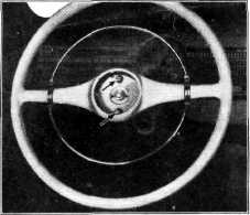
The
tension of the horn blowing ring, or load required on the ring to blow the horn, may be
adjusted by removing the
ornamental cap in the center of
the steering wheel, and turning the screws shown in Fig. 13, as
necessary. |
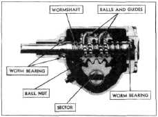
worm is welded integral to the
wormshaft as shown in Fig. 14. The
steering wheel is attached to the upper end of the wormshaft. The
worm is mounted between two barrel
type roller bearings, the lower one of which is adjustable toward
the upper, for removing end-play in the wormshaft. Between the roller
bearings, the worm is threaded with a precision-finished helical
groove.
The ball
nut is bored to clear the outside diameter of the worm as shown in
Fig. 15, and the bore is threaded
with a precision-finished helical groove corresponding to that in the worm. Within
the length of the nut the
helical grooves are filled with special steel balls of 9/32" diameter
(made to specifications specially drawn up for this steering gear).
There are two complete ball
circuits in the nut. To complete each circuit and keep the balls
from running out at the ends,
the nut is fitted with two tubular ball guides, each of which deflects
the balls from their helical
path when they reach the end of
the nut, returning them to the helical path in the nut at the start
of the circuit.
The two
ball guides, together with the helical grooves in the worm and nut. thus confine
the balls within two distinct
closed circuits, one in each end of the nut. The balls within the helical
path, 30 in each circuit, constitute a thread between the worm and
nut, so that when the worm is turned, the nut moves along the worm, as with an ordinary
screw thread. At the same time
the balls roll freely between
the worm and nut, circulating within their closed circuits, so that screw motion is
obtained with rolling instead
of sliding contact between the parts.
Rugged
rack teeth are cut in that portion of the nut which faces the sector as shown in Fig.
14.
The sector
shaft is mounted in anti-friction bronze bushings. A grease seal is provided
near the outer end of the sector shaft. The sector is provided
with rugged teeth which mesh
with the rack teeth of the nut.
These teeth are not ordinary spur gear teeth, but are produced by a special process
to provide true gear
action between the rack and sector when the nut is located at a slight angle.
With this construction, the adjustment for back-lash between the rack and sector teeth is very simple—all
that is required is to shift
the sector shaft slightly along its own axis by means of a convenient thrust
screw, known as a lash
adjuster.
The sector
teeth are purposely cut in such a way that, when the sector is adjusted to remove
all back-lash at the
straight-ahead position of the front wheels, there will be a slight
back-lash at each end of the
sector travel, or when the wheels are turned far to the right or left of
straight-ahead. In this way
snugness of the sector in the rack teeth can be maintained with the
wheels in |
||
 |
|||
|
Fig. 13—Horn Blowing Ring Tension Adjustment
Turning the screws clockwise
increases the tension, and
counterclockwise reduces it.
STEERING GEAR ASSEMBLY
CONSTRUCTION ALL CONVENTIONAL
TRUCKS
The truck steering gear, Fig. 14,
is of the recir-culating ball type. Steering gear ratio on all
conventional truck models is 19.8 to 1. |
|||
 |
|||
|
Fig. 14—Truck Steering Gear Worm. Nut and Ball
Circuits
The
principle working parts are the steering worm, the ball nut and the sector and
shaft. Each of these parts is
of heat-treated alloy steel. The |
|||
|
|
|||