1942 - 1947 CHEVROLET SHOP MANUAL
Section 9 - Steering Gear Assembly
|
|
|||
|
9-12 |
|||
|
|
|||
|
6. Fill the second ball circuit in the same
manner as the
first.
7. Assemble the ball guide clamp to the nut,
being sure to use lock washers
under the clamp screws and set
the screws up TIGHT.
Check the
sssembly by rotating the nut on the worm to see that it moves freely. Do not
rotate the nut to the end of the worm threads and thereby damage the ball guides. If there is any
"'stickiness" in the motion of
the nut, some slight damage to the ends of the ball guides may have been
overlooked.
Assembling Steering Gear
1. Lay the wormshaft and nut assembly flat on
the bench to make sure that
the nut does not run to the end
of the worm.
2. Place the upper roller bearing over the
wormshaft. Then thread
the wormshaft into the housing.
3. Back the worm bearing thrust screw out of
the lower end cover a few turns. Install the lower bearing. Assemble the end cover to the
housing, using a new
gasket.
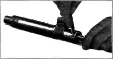
4. Assemble the lash adjuster with shim in the
slot in end of sector shaft.
Check the end clearance which
should not be greater than .002", Fig. 24. For the purpose of adjusting
this |
6. Rotate the wormshaft by hand until the ball
nut is about in the center of
travel. This is to make sure
that the rack and sector will engage properly, with the center tooth of the
sector entering the center
tooth space of the nut.
7. Push the side cover assembly, including the
sector shaft and side cover
gasket, into place. After
making sure there is some lash between the rack and sector teeth, assemble and
tighten the side cover
bolts.
Adjustment of Steering Gear on Bench
1. Tighten the worm bearing thrust screw until
all wormshaft end-play has been
removed. Then tighten the lock
nut.
2. Install the steering wheel on the wormshaft
temporarily. Carefully turn
the steering wheel all the way
in one direction and then back about one turn.
3. Using a J-544 steering gear checking scale,
at right angle to one spoke at
wheel rim, measure the pull
required to keep the wheel in motion. This should be between 1 and 1-1/2
pounds. If necessary,
adjust the worm thrust screw until the proper pull is
obtained.
4. Turn the steering wheel from one stop all
the way to the other, counting
the number of turns. Then turn
the wheel back exactly half the number of turns to the center position and
mark the wheel at the top or
bottom with a piece of tape.
5. Turn the sector lash adjuster screw
clockwise to remove all lash
between rack and sector teeth.
Tighten the lock nut.
NOTE—Be sure adjustment is not
changed while tightening the lock nut.
6. Using the J-544 steering gear checking
scale, check the pull at the rim of the steering wheel. Take the highest reading on the scale as
the wheel is pulled
through the center position. This should be between 2 and 2-1/2
pounds.
7. If necessary, readjust the lash adjuster
screw to obtain the proper pull. Tighten the lock nut and again check for proper
pull.
8. Fill the assembly with Steering Gear, "All
Purpose," or '"Universal"
gear lubricant to the level of
the filler plug hole and replace the filler plug.
When the
proper adjustments have been made and
the steering gear lubricated, the assembly is ready to be replaced in the truck. In doing
this make sure that no "bind" is set up when tightening the mounting bolts and mast jacket to
instrument panel
clamp. |
||
 |
|||
|
Fig. 24—Checking Sector Shaft Lash Adjuster End
Clearance
end
clearance, a steering gear lash adjuster shim unit, Part No. 605142, is available.
It contains four shims: .063", .065", .067", and .069" thick.
5. After the lash adjuster end
clearance has been adjusted start the
sector shaft pilot into the bushing in the side cover. Then, using
a screwdriver through the hole in
the cover, turn the lash adjuster in a counterclockwise direction
to pull the sector shaft pilot into
its bushing as far as it will go.
|
|||
|
|
|||