1942 - 1947 CHEVROLET SHOP MANUAL
Section 1 Body
|
|
|||
|
1-9
|
|||
|
|
|||
|
2. Remove
the screws attaching the door division
channel at the top and bottom of
the window opening.
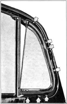
3. Remove
the screws attaching the ventilator
assembly to the window opening,
Fig. 17.
|
3. Turn
the ventilator glass to the closed position
and adjust the glass and frame up
or down as necessary to
provide the proper clearance for
the bottom of the frame on the
rubber weatherstrip.
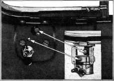
Install and tighten the ventilator shaft to
regulator bolt, Fig. 18.
4. Properly
line up the door division channel, then
install the screws attaching it
at the top and bottom of
the door opening.
5. Reassemble
the door trim pad, all handles, and
the door window garnish molding.
Ventilator Adjustments
Should a front door
ventilator glass and frame move too freely or develop excessive play
or travel in relation to regulator handle movement, correction may be
made as follows. Remove the door window garnish molding, loosen the
door trim pad at the top and down both sides about twelve inches to
expose the ventilator regulator. Tighten the ventilator shaft to
regulator bolt (top bolt in Fig. 18) which will reduce such excessive
play or movement.
|
||
 |
|||
 |
|||
|
Fig. 17-Ventilator Attaching Screws to Door
Opening
4. Remove the bolt
attaching the ventilator shaft to the regulator body, Fig. 18. Turn
the ventilator glass to about one-third open, then, while carefully
releasing the rubber weatherstrip, lift the ventilator assembly out of
the opening in the door.
Installation
1. Clean
all old rubber cement from the ventilator
opening in the door and from the
sealing surface of the
weatherstrip.
2. Coat
the edge of the door panel and the ventilator
rubber weatherstrip with FS-655 rubber
cement. Install the ventilator
assembly in the door
opening, making sure that the lip of the
rubber weatherstrip is properly
positioned over the edge
of the window reveal. Install the ventilator
attaching screws to the window opening.
|
|||
|
Fig. 18-Ventilator Shaft Bolt and Friction
Adjusting Screw
A ventilator regulator
which operates too freely or too hard, resulting in failure to remain
fully closed unless locked in case of the former, may be corrected by
tightening or loosening the friction clamp screw on the regulator
mechanism, lower screw shown in Fig. 18. This adjustment point is
reached by the same disassembly procedure outlined for the foregoing
adjustment.
Excessive play at the
ventilator glass frame upper pivot, which may develop after long
service, may be corrected by spreading apart the lower end of this
pivot which is slotted.
Ventilator Safety Locks
The sliding bolt type
ventilator safety lock is riveted to the ventilator glass frame, Fig.
19, and serves to prevent breaking into the car when locked by prying
the ventilator glass open.
|
|||
|
|
|||