1942 - 1947 CHEVROLET SHOP MANUAL
Section 2 - Frame
|
|
|||
|
2-14 |
|||
|
|
|||
|
3. Remove filler plug and drain fluid, working
arm back and forth until
completely drained.
4. Mount unit on assembly fixture at
bench.
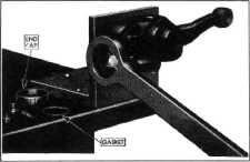
5. Remove both end caps, using special serrated
wrench J-766, Fig.
21. |
 |
||
 |
|||
|
Fig. 21 —Removing End Caps from
Double-ActIng Shock Absorbers |
|||
|
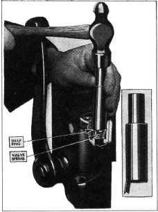
6. Remove valve spring retainer
clip with a screwdriver as shown in Fig. 22 and lift out
valve. |
|||
 |
|||
|
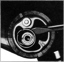
Fig. 23—Installing Valves and Snap Ring
After the valves have been
installed, flip the valve with a screwdriver to make sure that the valve
and spring are free. |
|||
 |
|||
|
Fig. 22—Removing Valve Spring Retainer
Clip
7. Install new valve and snap
ring, using special tool J-896, Fig. 23.
CAUTION—Be sure compression
valve is placed In the compression end of cylinder and rebound valve in
rebound end.
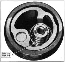
The open side of the snap ring
should be installed as shown in Fig. 24. If it is installed in any
other position it is very difficult to remove. |
|||
|
Fig. 24—Correct Position of Snap Ring
8. Replace one end cap, using new
gasket, and rotate fixture until open end of absorber is
up. |
|||
|
|
|||